STV0672 データシートの表示(PDF) - STMicroelectronics
部品番号
コンポーネント説明
メーカー
STV0672 Datasheet PDF : 41 Pages
| |||
STV0672-chipsetf-3-1.fm
Introduction
modified) once per frame, where a frame consists of 2 video fields. The video fields are identical in length, that is they do not
contain any of the half line detail of the analogue video standards like CCIR or NTSC. Two fields per frame are required by the
internal sensor video timing model. Integration time, sensor analogue gain and STV0672 digital gain are all used to control the
overall exposure. The STV0672 exposure algorithm uses an asymptotic approach in calculating the change required in the
present exposure value to approach the requested exposure target.
2.2.3 Defect Correction
STV0672 automatically detects and corrects for pixel defects, without the need for any additional components or additional
sensor calibration procedures. This greatly simplifies camera assembly and test, when compared with previous EEPROM-based
defect correction schemes. The pixel defect correction scheme in STV0672 ensures that VV6410+STV0672 and
VV6500+STV0672 are ‘defect free’ chipsets.
2.2.4 Interpolation
The Bayer pattern from the sensor provides under-sampled trichromatic data. Interpolation up-samples these undersampled data
streams to restore a bandlimited (effectively blurred) version of the original, using simple two-dimensional filtering templates.
Signal components aliased in the under-sampling process remain aliased after interpolation. The green channel (no longer
containing notions of even and odd rows) is treated differently from red and blue, being interpolated into two output
representations, one ‘sharper’ (containing more high-frequency detail) than the other. The smoother of the two green signals is
output along with red and blue to the matrix block.
2.2.5 Unsharp masking
Subtraction of these two green representations creates an ‘unsharp mask’, which can be further processed before adding back
into the main colour flow. The unsharp signal undergoes variable coring (a central thresholding operation for noise reduction) and
intensity (gain operation on the cored signal). The strain parameter from the housekeeper acts as both a coring threshold and an
attenuator on the user intensity setting, achieving a softening of image appearance in low-light conditions.
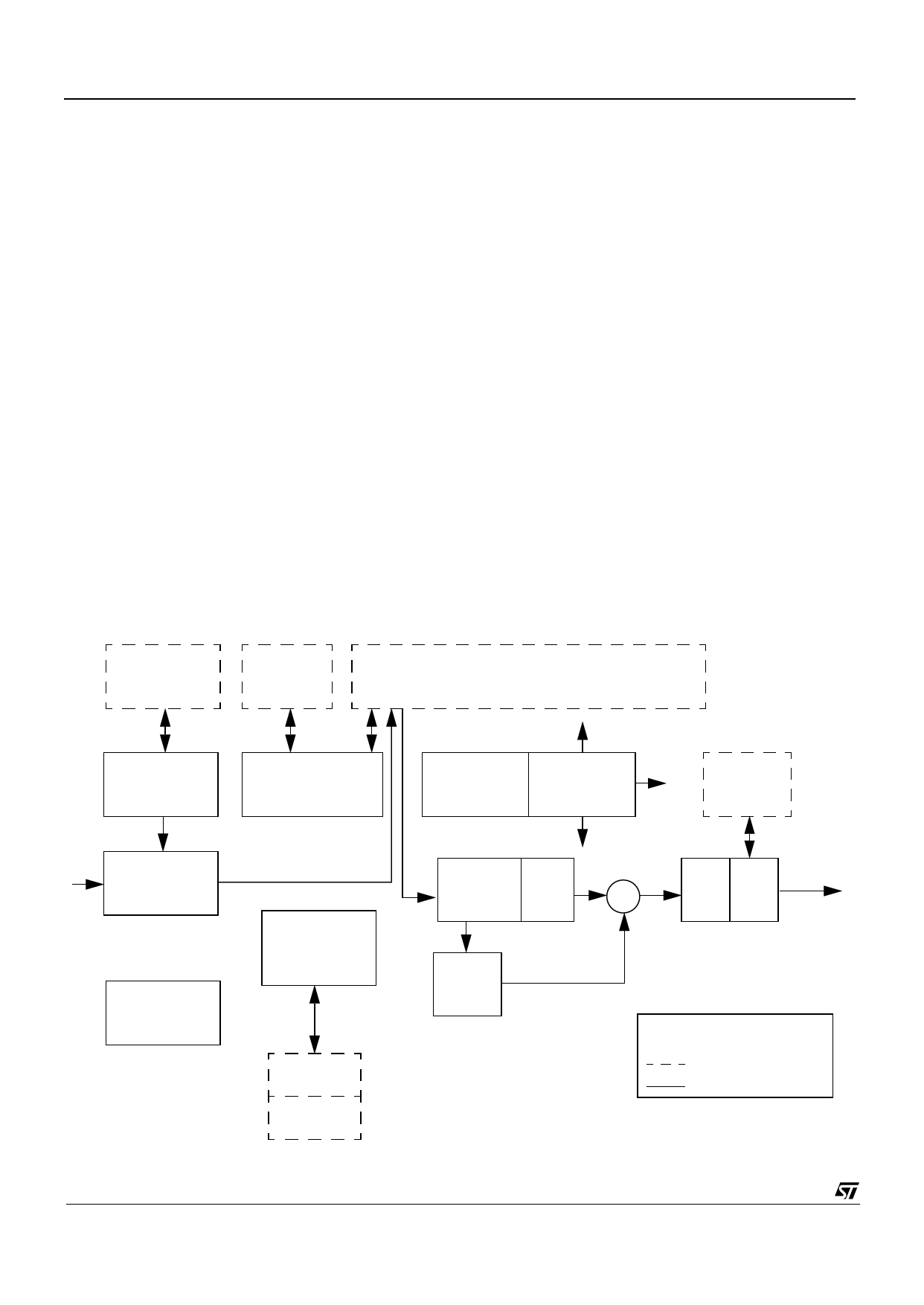
FPN Vector
(644x14)
Defect Map
(128x32)
Line Store
(9x644x10)
FPN Cancel
Defect
Detect & Correct
Control
Address Gen (All Sub Blocks)
QVGA FIFO
IN
Input Processor
Set-Up
Registers
6/41
House Keeper
(AEC,AGC,
AWB etc)
RAM
ROM
interpolation Matrix
+
YCbCr
Gamma 4:2:2
Encoder
OUT
Peaking
Key
===
Ram/Data Storage
Logic
Figure 2 : STV0672 VP Block Diagram
29 November 2000
Commercial in confidence
Share Link: 