24C02 データシートの表示(PDF) - Estek Electronics Co. Ltd
部品番号
コンポーネント説明
メーカー
24C02 Datasheet PDF : 13 Pages
| |||
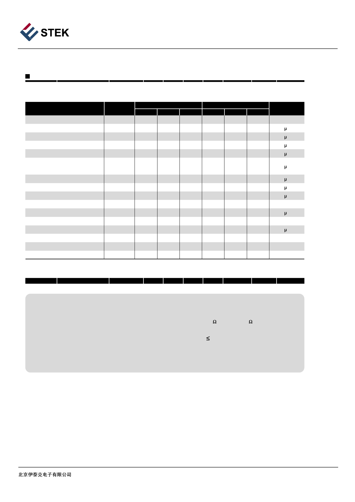
24C02 / 24C04 / 24C08 / 24C16
AC Electrical Characteristics
¡Applicable over recommended operating range from TA = -40。C to +85。C, VCC = +1.8V to +5.5V, CL = 1 TTL Gate and
100 pF (unless otherwise noted)
Parameter
Symbol
1.8-volt
5.0-volt
Min.
Typ.
Max.
Min.
Typ.
Max.
Units
Clock Frequency, SCL
fSCL
-
-
400
-
-
1000
kHz
Clock Pulse Width Low
tLOW
1.2
-
-
0.6
-
-
s
Clock Pulse Width High
tHIGH
0.6
-
-
0.4
-
-
s
Noise Suppression Time
tI
-
-
50
-
-
40
s
Clock Low to Data Out Valid
tAA
0.05
-
0.9
0.05
-
0.55
s
Time the bus must be free before
a new transmission can start
tBUF
1.2
-
-
0.5
-
-
s
Start Hold Time
Start Setup Time
Data In Hold Time
Data In Setup Time
Inputs Rise Time(1)
Inputs Fall Time(1)
Stop Setup Time
Data Out Hold Time
Write Cycle Time
5.0V, 25。C, Byte Mode
tHD.STA
0.6
-
-
0.25
-
-
s
tSU.STA
0.6
-
-
0.25
-
-
s
tHD.DAT
0
-
-
0
-
-
s
tSU.DAT
100
-
-
100
-
-
ns
tR
-
-
0.3
-
-
0.3
s
tF
-
-
300
-
-
100
ns
tSU.STO
0.6
-
-
0.25
-
-
s
tDH
50
-
-
50
-
-
ns
tWR
-
-
5
-
-
5
ms
Endurance
1M
-
-
-
-
-
Write Cycles
Note
1. This parameter is characterized and is not 100% tested.
2. AC measurement conditions:
RL (connects to VCC): 1.3 k (2.5V, 5V), 10 k (1.8V)
Input pulse voltages: 0.3 VCC to 0.7 VCC
Input rise and fall time: 50 ns
Input and output timing reference voltages: 0.5 VCC
The value of RL should be concerned according to the actual loading
on the user's system.
BEIJING ESTEK ELECTRONICS CO.,LTD
10
Share Link: 