3843CMTR-E1 データシートの表示(PDF) - BCD Semiconductor
部品番号
コンポーネント説明
メーカー
3843CMTR-E1 Datasheet PDF : 13 Pages
| |||
Data Sheet
CURRENT MODE PWM CONTROLLER
Electrical Characteristics (Continued)
AP384XC
Parameter
Symbol
Conditions
UNDER -VOLTAGE LOCKOUT SECTION
Start Threshold
VTH(ST)
AP3842C/AP3844C
AP3843C/AP3845C
Min. Operation Voltage
(After Turn On)
VOPR
(Min.)
AP3842C/AP3844C
AP3843C/AP3845C
PWM SECTION
Max. Duty Cycle
D(Max.)
D(Max.)
AP3842C/AP3843C
AP3844C/AP3845C
Min. Duty Cycle
D(Min.)
TOTAL STANDBY CURRENT SECTION
Start-Up Current
IST
Operating Supply Current
ICC(OPR) Vpin3=Vpin2=0V
Zener Voltage
VZ
ICC=25mA
OVER-TEMPERATURE PROTECT SECTION
Shutdown Temperature
Temperature Hysteresis
TSHUT
THYS
(Note 6)
(Note 6)
Min Typ Max Unit
15
16
17
V
7.8
8.4
9.0
V
8.5
10.0 11.5
V
7.0
7.6
8.2
V
95
97
100
%
46
48
50
%
0
%
50
80
µA
8
12
mA
30
34
V
155
oC
25
oC
Note 4: Parameters are tested at trip point of latch with Vpin2 = 0.
Note 5: Here gain is defined as:
∆VPin 1
A=
, 0 ≤ Vpin3 ≤ 0.8V
∆VPin 3
Note 6: These parameters, although guaranteed, are not 100% tested in production.
Note 7: This parameter is measured with RT=10kΩ to VREF, it contributes 0.3mA of current to the measured value.
So the total current flowing into the CT pin will be 0.3mA higher than the measured value approximately.
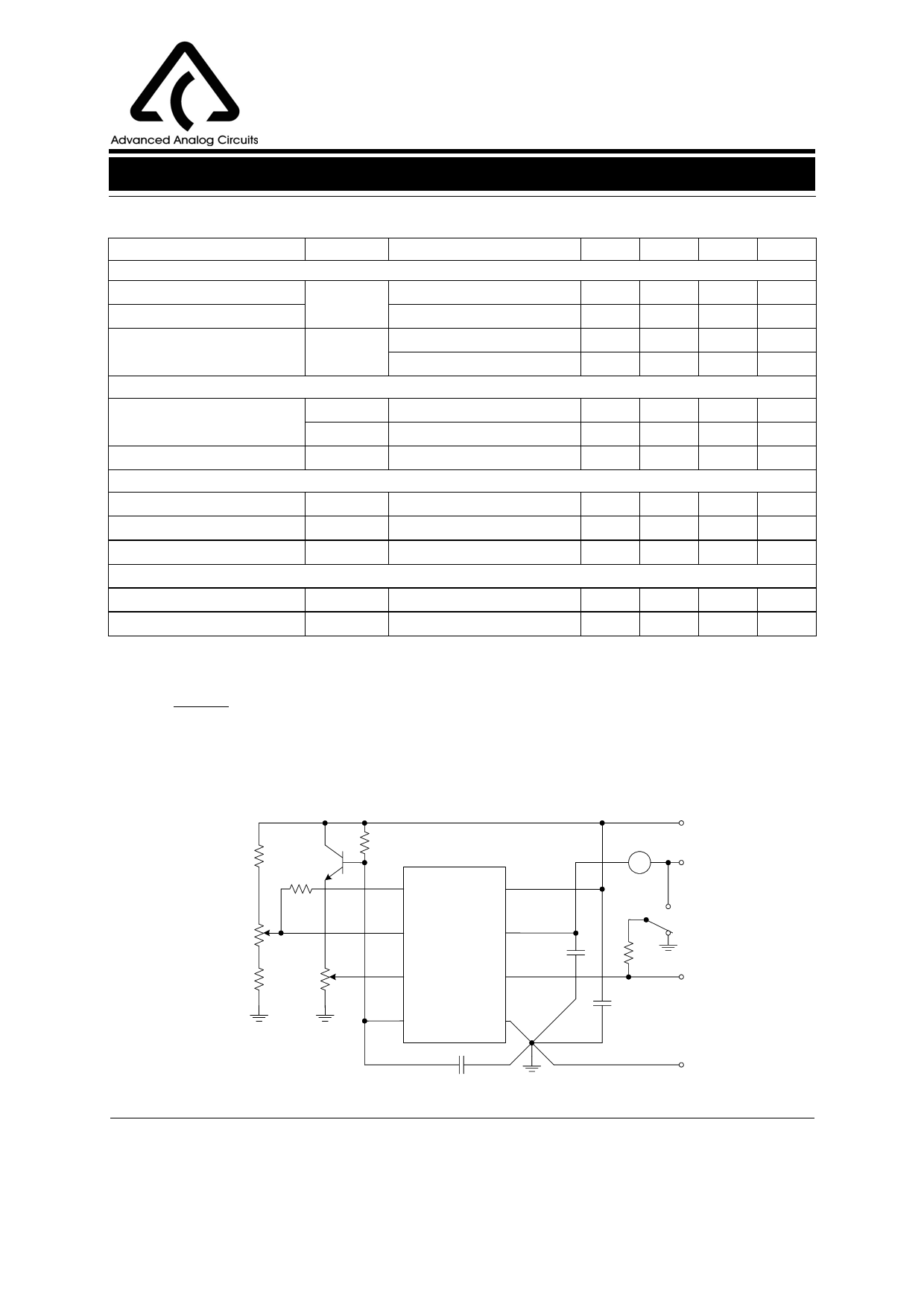
4.7k
2N2222
1k
ERROR AMP
ADJUST
4.7k
100k
5k
ISENSE
ADJUST
RT
AP384XC
1 COMP
VREF 8
2 VFB
VCC 7
3 ISENSE OUTPUT 6
0.1µF
4 RT/CT
GND 5
VREF
A
VCC
1K
1W
0.1µF
OUTPUT
Sep. 2006 Rev. 1. 1
CT
Figure 4. Basic Test Circuit
GND
BCD Semiconductor Manufacturing Limited
7
Share Link: 