BL1062A1 データシートの表示(PDF) - Shanghai Belling Co., Ltd.
部品番号
コンポーネント説明
メーカー
BL1062A1 Datasheet PDF : 7 Pages
| |||
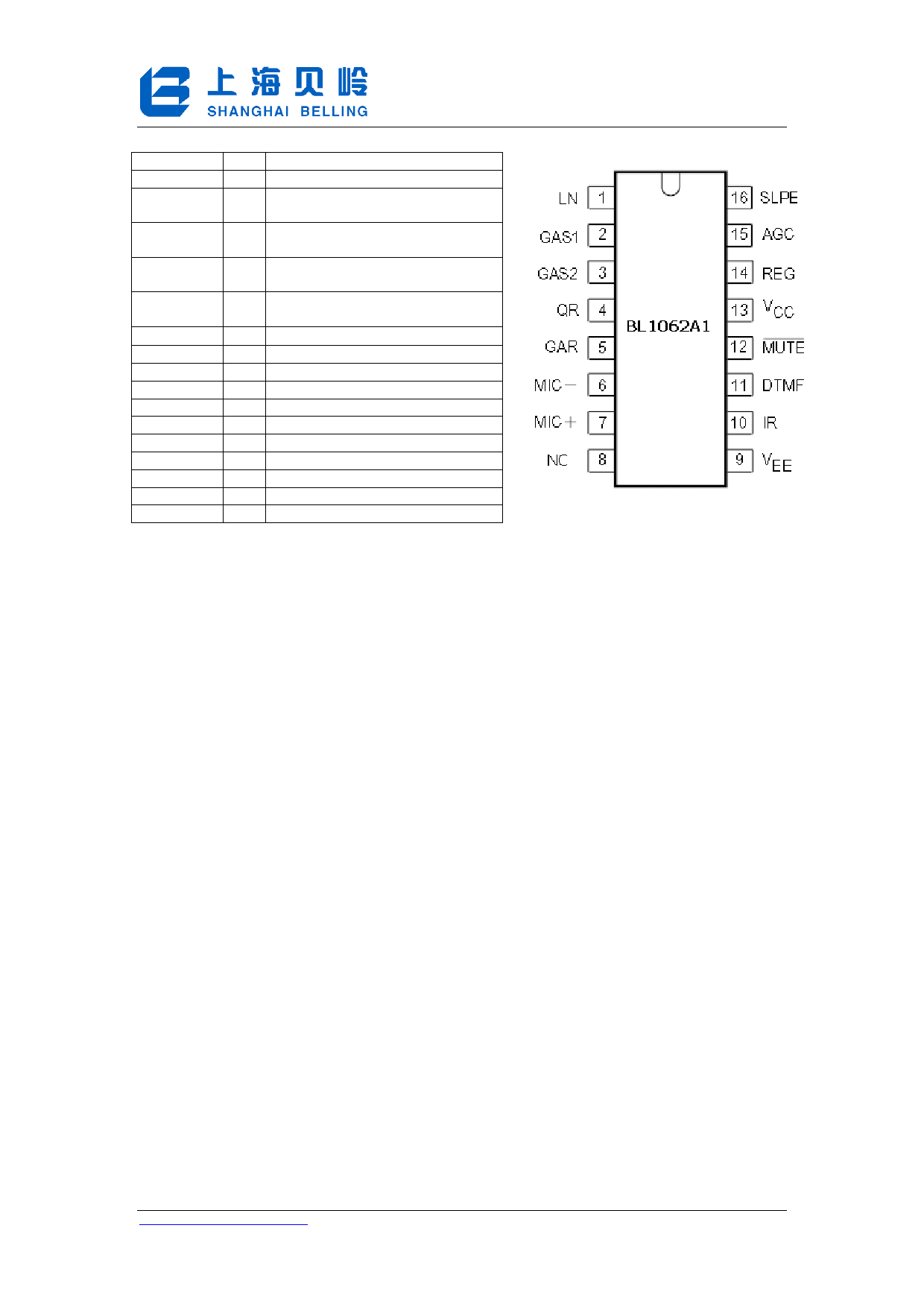
4. Pin Configurations, Definitions
SYMBOL
LN
GAS1
GAS2
QR
GAR
MIΧ−
MIC+
NC
VEE
IR
DTMF
MUTE
VCC
REG
AGC
SLPE
PIN
DESCRIPTION
1 positive line terminal
2 gain adjustment; transmitting
amplifier
3 gain adjustment; transmitting
amplifier
4 non-inverting output; receiving
amplifier
5 gain adjustment; receiving
amplifier
6 Inverting microphone input
7 non-inverting microphone input
8 NC
9 Negative line terminal
10 Receiving amplifier input
11 dual-tone multi-frequency input
12 mute input (see note 1)
13 positive supply decoupling
14 voltage regulator decoupling
15 automatic gain control input
16 slope (DC resistance) adjustment
BL1062A1
5. Function Description
Supplies VCC , LN, SLPE, REG
Power for the IC and its peripheral circuits is usually obtained from the telephone line. The
supply voltage is derived from the line via a dropping resistor and regulated by the IC. The supply
voltage VCC may also be used to supply external circuits e.g. dialling and control circuits.
Decoupling of the supply voltage is performed by a capacitor between VCC and VEE . The internal
voltage regulator is decoupled by a capacitor between REG and VEE . The DC current flowing into
the set is determined by the exchange supply voltage Vexch, the feeding bridge resistance Rexch
and the DC resistance of the telephone line Rline .
At line currents below 9 mA the internal reference voltage is automatically adjusted to a lower
value (typically 1.6 V at 1 mA). This means that more sets can be operated in parallel with DC line
voltages (excluding the polarity guard) down to an absolute minimum voltage of 1.6 V. At line
currents below 9 mA the circuit has limited sending and receiving levels. The internal reference
voltage can be adjusted by means of an external resistor (RVA ). This resistor when connected
between LN and REG will decrease the internal reference voltage and when connected between
REG and SLPE will increase the internal reference voltage.
Microphone inputs MIC+ and MIC− and gain pins GAS1 and GAS2
The circuit has symmetrical microphone inputs. Its input impedance is 64 kΩ (2 x 32 kΩ) and
its voltage gain is typically 52 dB (when R7 = 68 kΩ, see Figures 2 and 3). Dynamic, magnetic,
piezoelectric or electret (with built-in FET source followers) can be used. The gain of the
microphone amplifier can be adjusted between 44 dB and 52 dB to suit the sensitivity of the
transducer in use. The gain is proportional to the value of R7, which is connected between GAS1
and GAS2.
http://www.belling.com.cn
-2-
Total 7 Pages
8/25/2006
Wrote by 2006
Share Link: 