EBT156 データシートの表示(PDF) - Vishay Semiconductors
部品番号
コンポーネント説明
メーカー
EBT156
Vishay Semiconductors

EBT156 Datasheet PDF : 4 Pages
| |||
www.vishay.com
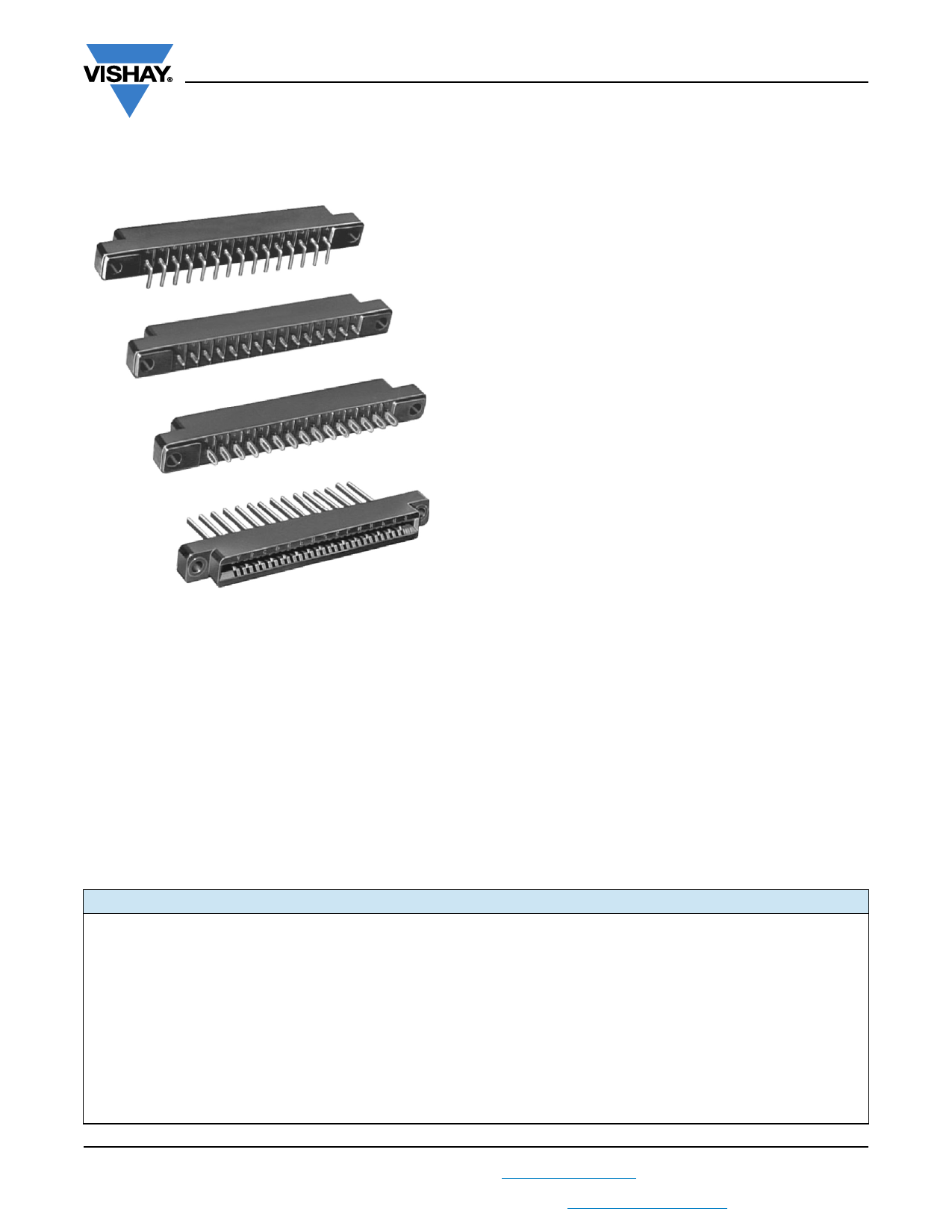
EBT156
Vishay Dale
Edgeboard Connectors, Single Readout, Dip Solder, Eyelet and
Wire Wrap™ Termination
FEATURES
• 0.156" (3.96 mm) C-C
• Modified tuning fork contacts have chamfered lead-in to
reduce wear on printed circuit board contacts without
sacrificing contact pressure and wiping action
• Accepts PC board thickness of 0.054" to 0.070" (1.37 mm
to 1.78 mm)
• Polarization on or between contact positions in all sizes.
Between contact polarization permits polarizing without
loss of a contact position
• Polarizing key is reinforced nylon, may be inserted by
hand, requires no adhesive
• Protected entry, provided by recessed leading edge of
contact, permits the card slot to straighten and align the
board before electrical contact is made. Prevents damage
to contacts which might be caused by warped or out of
tolerance boards
• Optional terminal configurations, including eyelet (type A),
dip-solder (types B, C, D, R), Wire Wrap™ (types E, F)
ELECTRICAL SPECIFICATIONS
Current Rating: 5 A
Test Voltage Between Contacts:
at sea level: 1800 VRMS
At 70 000 feet (21 336 meters): 450 VRMS
Insulation Resistance: 5000 M minimum (at 500 VDC
potential)
Contact Resistance: (voltage drop) 30 mV maximum at
rated current with gold flash
PHYSICAL SPECIFICATIONS
Number of Contacts: 6, 10, 12, 15, 18, or 22
Contact Spacing: 0.156" (3.96 mm)
Card Thickness: 0.054" to 0.070" (1.37 mm to 1.78 mm)
Card Slot Depth: 0.330" (8.38 mm)
APPLICATIONS
For use with 0.062" (1.57 mm) printed circuit boards requiring
an edgeboard type connector on 0.156" (3.96 mm) centers
MATERIAL SPECIFICATIONS
Body: glass-filled phenolic per MIL-M-14, type MFH, black,
flame retardant (UL 94 V-0)
Contacts: copper alloy
Finish: 1 = electro tin plated, 2 = gold flash
Polarizing Key: glass-filled nylon
Optional Threaded Mounting Insert: nickel plated brass
(type Y)
Optional Floating Mounting Bushing: cadmium plated
brass (type Z)
ORDERING INFORMATION
EBT156
MODEL
10
CONTACTS
6, 10, 12,
15, 18, or 22
A
1
X
A, J
STANDARD TERMINAL CONTACT MOUNTING BETWEEN CONTACT
VARIATIONS
FINISH VARIATIONS POLARIZATION
A, B, C, D,
E, F, or R
1 = Electro tin W, X, Y, or Z
plated
2 = Gold flash
Required only when polarizing key(s) are to be
factory installed.
Polarization key positions: Between contact
polarization key(s) are located to the right of the
contact position(s) desired.
Example: A, J means keys between A and B,
and J and K
A9, J9
ON CONTACT POLARIZATION
Required only when polarizing
key(s) are to be factory installed.
Polarization key replaces contact.
When polarizing key(s) replaces
contact(s), indicate by adding
suffix “9” to contact position(s)
desired.
Example: A9, J9 means keys
replace terminals A and J
Revision: 29-Mar-2019
1
Document Number: 36007
For technical questions, contact: connectors@vishay.com
THIS DOCUMENT IS SUBJECT TO CHANGE WITHOUT NOTICE. THE PRODUCTS DESCRIBED HEREIN AND THIS DOCUMENT
ARE SUBJECT TO SPECIFIC DISCLAIMERS, SET FORTH AT www.vishay.com/doc?91000
Share Link: