HT48R70A-1 データシートの表示(PDF) - Holtek Semiconductor
部品番号
コンポーネント説明
メーカー
HT48R70A-1 Datasheet PDF : 39 Pages
| |||
HT48R70A-1/HT48C70-1
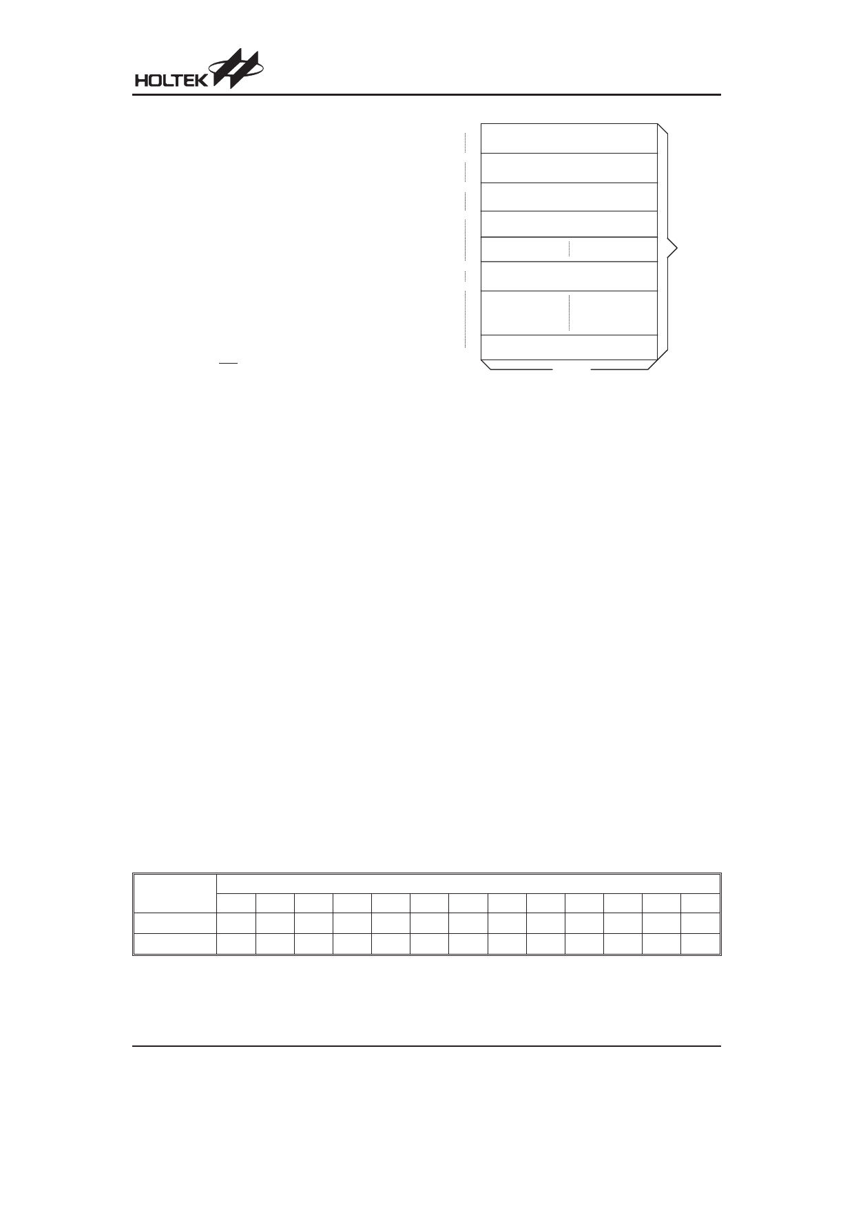
Program Memory - ROM
The program memory is used to store the program in-
structions which are to be executed. It also contains
data, table, and interrupt entries, and is organized into
8192´16 bits, addressed by the program counter and ta-
ble pointer.
Certain locations in the program memory are reserved
for special usage:
· Location 000H
This area is reserved for program initialization. After
chip reset, the program always begins execution at lo-
cation 000H.
· Location 004H
This area is reserved for the external interrupt service
program. If the INT interrupt pin is activated, the inter-
rupt enabled and the stack is not full, the program be-
gins execution at location 004H.
· Location 008H
This area is reserved for the Timer/Event Counter 0 in-
terrupt service program. If a timer interrupt results from a
Timer/Event Counter 0 overflow, and if the interrupt is
enabled and the stack is not full, the program begins ex-
ecution at location 008H .
· Location 00CH
This location is reserved for the Timer/Event Counter
1 interrupt service program. If a timer interrupt results
from a Timer/Event Counter 1 overflow, and the inter-
rupt is enabled and the stack is not full, the program
begins execution at location 00CH.
· Table location
Any location in the program memory can be used as
look-up tables. The instructions ²TABRDC [m]² (the
current page, one page=256 words) and ²TABRDL
[m]² (the last page) transfer the contents of the
lower-order byte to the specified data memory, and
the higher-order byte to TBLH (08H). The Table
Higher-order byte register (TBLH) is read only. The ta-
ble pointer (TBLP) is a read/write register (07H),
which indicates the table location. Before accessing
the table, the location must be placed in the TBLP. The
TBLH is read only and cannot be restored. If the main
routine and the ISR (Interrupt Service Routine) both
employ the table read instruction, the contents of the
TBLH in the main routine are likely to be changed by
000H
D e v ic e In itia liz a tio n P r o g r a m
004H
E x te r n a l In te r r u p t S u b r o u tin e
008H
T im e r /E v e n t C o u n te r 0
In te r r u p t S u b r o u tin e
00C H
T im e r /E v e n t C o u n te r 1
In te r r u p t S u b r o u tin e
n00H
L o o k - u p T a b le ( 2 5 6 w o r d s )
nFFH
P ro g ra m
M e m o ry
1FFFH
L o o k - u p T a b le ( 2 5 6 w o r d s )
1 6 b its
N o te : n ra n g e s fro m 0 to 1 F
Program Memory
the table read instruction used in the ISR. Errors can
occur. In other words, using the table read instruction
in the main routine and the ISR simultaneously should
be avoided. However, if the table read instruction has
to be applied in both the main routine and the ISR, the
interrupt is supposed to be disabled prior to the table
read instruction. It will not be enabled until the TBLH
has been backed up. All table related instructions re-
quire two cycles to complete the operation. These ar-
eas may function as normal program memory
depending upon the requirements.
Stack Register - STACK
This is a special part of the memory which is used to
save the contents of the program counter only. The
stack is organized into 16 levels and is neither part of the
data nor part of the program space, and is neither read-
able nor writeable. The activated level is indexed by the
stack pointer (SP) and is neither readable nor writeable.
At a subroutine call or interrupt acknowledge signal, the
contents of the program counter are pushed onto the
stack. At the end of a subroutine or an interrupt routine,
signaled by a return instruction (RET or RETI), the pro-
gram counter is restored to its previous value from the
stack. After a chip reset, the SP will point to the top of the
stack.
Table Location
Instruction
*12 *11 *10 *9 *8 *7 *6 *5 *4 *3 *2 *1 *0
TABRDC [m] P12 P11 P10 P9 P8 @7 @6 @5 @4 @3 @2 @1 @0
TABRDL [m] 1
1
1
1
1 @7 @6 @5 @4 @3 @2 @1 @0
Note: *12~*0: Table location bits
@7~@0: Table pointer bits
Table Location
P12~P8: Current program counter bits
Rev. 2.10
7
August 7, 2007
Share Link: 