HT48C10-1 データシートの表示(PDF) - Holtek Semiconductor
部品番号
コンポーネント説明
メーカー
HT48C10-1 Datasheet PDF : 38 Pages
| |||
HT48R10A-1/HT48C10-1
Bit No.
0
1
2
3
4
5
6
7
Label
EMI
EEI
ETI
¾
EIF
TF
¾
¾
Function
Controls the master (global) interrupt (1= enabled; 0= disabled)
Controls the external interrupt (1= enabled; 0= disabled)
Controls the timer/event counter interrupt (1= enabled; 0= disabled)
Unused bit, read as ²0²
External interrupt request flag (1= active; 0= inactive)
Internal timer/event counter request flag (1= active; 0= inactive)
Unused bit, read as ²0²
Unused bit, read as ²0²
INTC (0BH) Register
The timer/event counter interrupt request flag (TF), ex-
ternal interrupt request flag (EIF), enable timer/event
counter bit (ETI), enable external interrupt bit (EEI) and
enable master interrupt bit (EMI) constitute an interrupt
control register (INTC) which is located at 0BH in the
data memory. EMI, EEI, ETI are used to control the en-
abling/disabling of interrupts. These bits prevent the re-
quested interrupt from being serviced. Once the
interrupt request flags (TF, EIF) are set, they will remain
in the INTC register until the interrupts are serviced or
cleared by a software instruction.
It is recommended that a program does not use the
²CALL subroutine² within the interrupt subroutine. In-
terrupts often occur in an unpredictable manner or
need to be serviced immediately in some applications.
If only one stack is left and enabling the interrupt is not
well controlled, the original control sequence will be dam-
aged once the ²CALL² operates in the interrupt subrou-
tine.
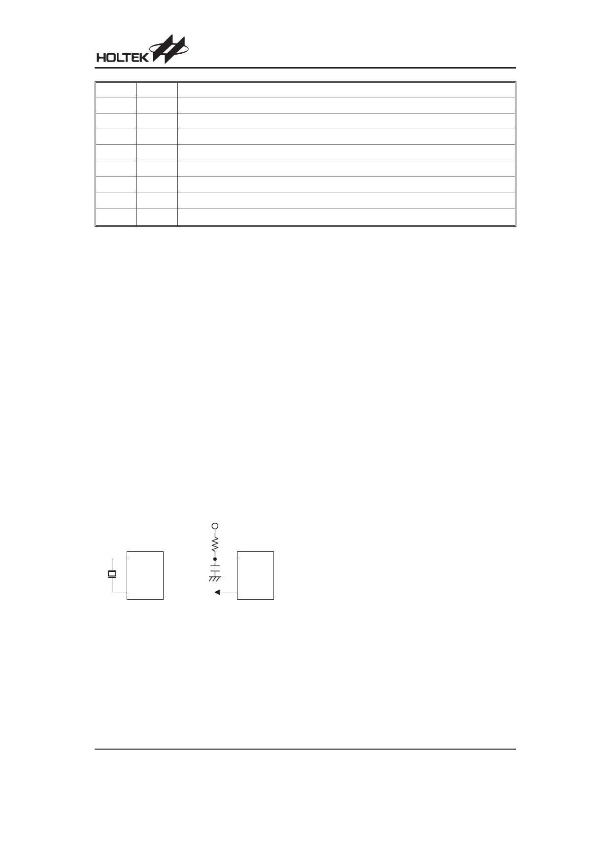
Oscillator Configuration
There are 3 oscillator circuits in the microcontroller.
V DD
O SC1
470pF
O SC1
O SC2
fS Y S /4
O SC2
N M O S O p e n D r a in
C r y s ta l O s c illa to r
R C O s c illa to r
( In c lu d e 3 2 7 6 8 H z )
System Oscillator
All of them are designed for system clocks, namely the
external RC oscillator, the external Crystal oscillator and
the internal RC oscillator, which are determined by the
options. No matter what oscillator type is selected, the
signal provides the system clock. The HALT mode stops
the system oscillator and ignores an external signal to
conserve power.
If an RC oscillator is used, an external resistor between
OSC1 and VDD is required and the resistance must
range from 24kW to 1MW. The system clock, divided by
4, is available on OSC2, which can be used to synchro-
nize external logic. The RC oscillator provides the most
cost effective solution. However, the frequency of oscil-
lation may vary with VDD, temperatures and the chip it-
self due to process variations. It is, therefore, not
suitable for timing sensitive operations where an accu-
rate oscillator frequency is desired.
If the Crystal oscillator is used, a crystal across OSC1
and OSC2 is needed to provide the feedback and phase
shift required for the oscillator, and no other external
components are required. Instead of a crystal, a resona-
tor can also be connected between OSC1 and OSC2 to
get a frequency reference, but two external capacitors in
OSC1 and OSC2 are required. If the internal RC oscilla-
tor is used, the OSC1 and OSC2 can be selected as
general I/O lines or an 32768Hz crystal oscillator (RTC
OSC). Also, the frequencies of the internal RC oscillator
can be 3.2MHz, 1.6MHz, 800kHz and 400kHz (de-
pended by options).
The WDT oscillator is a free running on-chip RC oscillator,
and no external components are required. Even if the sys-
tem enters the power down mode, the system clock is
stopped, but the WDT oscillator still works with a period of
approximately 65ms@5V. The WDT oscillator can be dis-
abled by options to conserve power.
Watchdog Timer - WDT
The clock source of WDT is implemented by a dedicated
RC oscillator (WDT oscillator), RTC clock or instruction
clock (system clock divided by 4), decided by options.
This timer is designed to prevent a software malfunction
or sequence from jumping to an unknown location with
unpredictable results. The Watchdog Timer can be dis-
abled by an option. If the Watchdog Timer is disabled, all
the executions related to the WDT result in no operation.
The RTC clock is enabled only in the internal RC+RTC
mode.
Rev. 1.90
10
November 4, 2005
Share Link: 