MAX11080GUU データシートの表示(PDF) - Maxim Integrated
部品番号
コンポーネント説明
メーカー
MAX11080GUU Datasheet PDF : 29 Pages
| |||
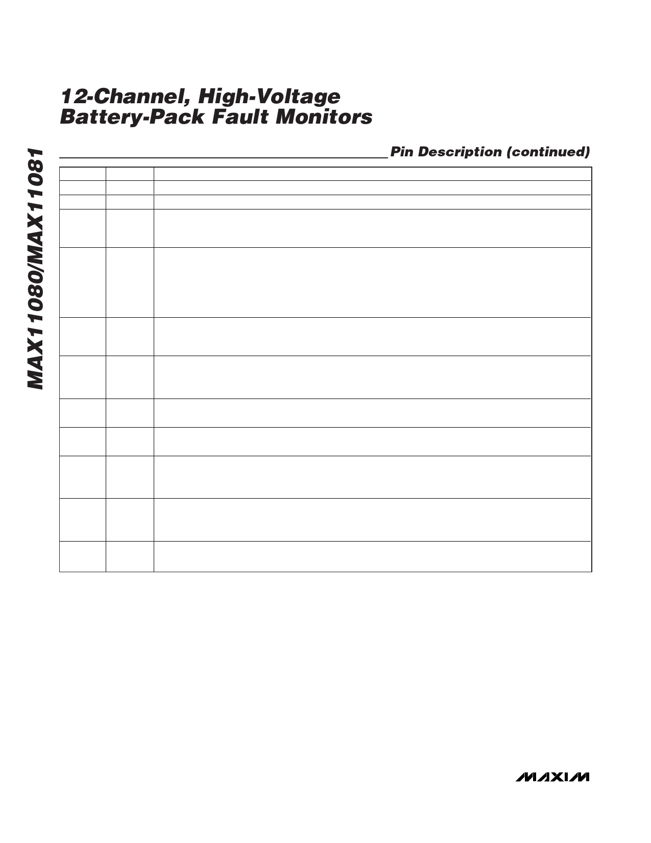
12-Channel, High-Voltage
Battery-Pack Fault Monitors
Pin Description (continued)
PIN
NAME
FUNCTION
24
VAA +3.3V Analog Supply Output. Bypass with a 1µF capacitor to AGND.
25
AGND Analog Ground. Should be connected to the negative terminal of cell 1.
Active-Low Shutdown Input. This pin completely shuts down the MAX11080/MAX11081 internal regulators
26
SHDN and oscillators when the pin is less than 0.6V as referenced to AGND. The host controller should drive
SHDN for the first pack. See Figure 2 for the SHDN daisy-chained module connection.
Lower Port Alarm Output. This output is an alarm indicator for overvoltage, undervoltage, and setup faults.
The alarm signal is daisy-chained and driven from the highest module down to the lowest. The alarm output
27
ALRML
is nominally a clocked “heartbeat” signal that provides a 4kHz clock when no alarm is present. The ALRML
can also be configured as level signal and set to “low” for no alarm and “high” for alarm state. See the
TOPSEL Function section for details. This signal swings between VAA and AGND, and is active high in the
alarm state.
Programmable Delay Time. Connect a capacitor from this pin to AGND to set the hold time required for a
28
CD fault condition before the alarm is set. The capacitor should be a ceramic capacitor in the 15nF to 16.5µF
range.
29, 30, 32
TST1,
TST2,
TST3
Production Test Pins. Connect to AGND.
31
TOPSEL Input to Indicate Topmost Device in the Daisy-Chain. This pin should be connected to AGND for all devices
except the topmost. For the top device, this pin should be connected to VAA.
34
ALRMU
Upper Port Alarm Input. This input receives the ALRML output signal from an upper neighboring module. It
swings between VDDU and GNDU.
Level-Shifted Upper Port Ground. Upper port-supply return and supply input for the charge-pump supply.
35
GNDU This pin should be connected to the DCIN takeoff point on the battery stack as shown in the application
diagrams.
36
37, 38
VDDU
Level-Shifted Upper Port Supply. Upper port-supply output for the daisy-chained bus. This is a regulated
output voltage from the internal charge pump that is level-shifted above the DCIN pin voltage level. It
should be bypassed with a 1µF capacitor to GNDU.
CP-, CP+ Charge-Pump Capacitor. Negative/positive input for the internal charge pump. Connect a 0.01µF high-
voltage capacitor between CP+ and CP-.
6 _______________________________________________________________________________________
Share Link: 