MAX1832 データシートの表示(PDF) - Maxim Integrated
部品番号
コンポーネント説明
メーカー
MAX1832 Datasheet PDF : 12 Pages
| |||
High-Efficiency Step-Up Converters with
Reverse Battery Protection
PIN
MAX1832
MAX1834
MAX1833
MAX1835
1
1
2
2
3
3
4
4
5
5
6
—
—
6
Pin Description
NAME
FUNCTION
SHDN
BATT
GND
LX
OUT
FB
RST
Shutdown. A high logic level turns on the device. When SHDN is low the part is off,
and the current into BATT is typically 0.1µA. For the MAX1832/MAX1833, the
battery is connected to OUT through an internal PFET and the external inductor
when SHDN is low. SHDN can be used for low-battery cutoff (1.228V threshold).
See Low-Battery Cutoff. SHDN has reverse battery protection.
Battery Voltage Connection. BATT has reverse battery protection.
Ground
Inductor Connection. N-channel MOSFET switch drain and synchronous
rectifier P-channel switch drain. LX has reverse battery protection.
Output Voltage. Bootstrapped supply for the device. Output sense point for
MAX1833/MAX1835.
MAX1832/MAX1834 Feedback Input. Set the output voltage through a
resistor-divider network. See Setting the Output Voltage.
MAX1833/MAX1835 Power-On Reset Open-Drain Output. RST pulls low when
the output is 10% below the regulation point. If not used, connect to GND.
RST is high impedance in shutdown.
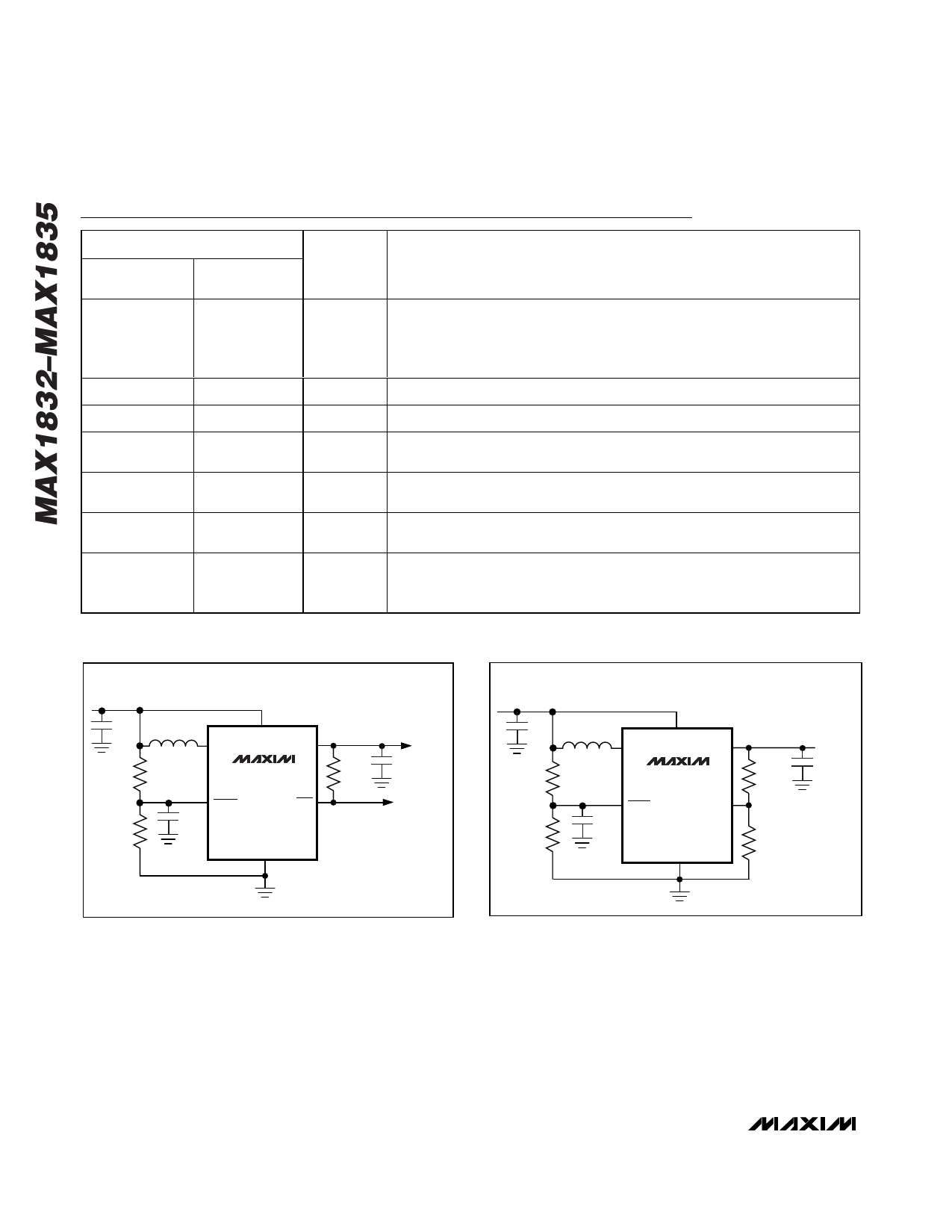
+1.5V TO +3.3V
BATTERY
10µF
R4
220kΩ
R3
1MΩ
10µH
LX
BATT
OUT
MAX1833
MAX1835
SHDN
RST
C1
10nF
GND
100kΩ
OUTPUT
+3.3V
10µF
POWER-ON
RESET
+1.5V TO +5.0V
BATTERY
10µF
10µH
LX
BATT
OUT
R4
220kΩ
R3
1MΩ
MAX1832
MAX1834
SHDN
FB
C1
10nF
GND
R2
309kΩ
R1
100kΩ
OUTPUT
+5.0V
Figure 1a. MAX1833/MAX1835 Typical Operating Circuit
Figure 1b. MAX1832/MAX1834 Typical Operating Circuit
6 _______________________________________________________________________________________
Share Link: 