MAX212C データシートの表示(PDF) - Maxim Integrated
部品番号
コンポーネント説明
メーカー
MAX212C Datasheet PDF : 8 Pages
| |||
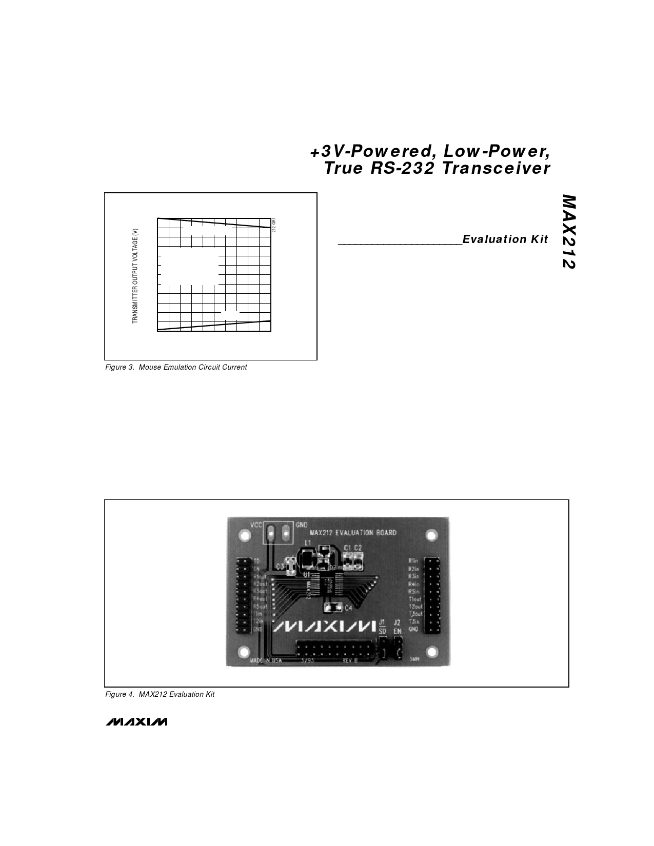
TRANSMITTER OUTPUT VOLTAGE vs.
LOAD CURRENT PER TRANSMITTER
6
T1OUT AND T2OUT
4
2
T1IN AND T2IN = GND,
T3IN = VCC = 3.0V,
T3OUT, T2OUT, T1OUT
0 ALL LOADED
SIMULTANEOUSLY
-2
-4
T3OUT
-6
1
2
3
4
5
6
LOAD CURRENT PER TRANSMITTER (mA)
Figure 3. Mouse Emulation Circuit Current
+3V-Powered, Low-Power,
True RS-232 Transceiver
Maxim’s MAX560 and MAX561 are EIA/TIA-562 trans-
ceivers that operate on a single supply from 3.0V to
3.6V, and the MAX562 transceiver operates from 2.7V
to 5.25V while producing EIA/TIA-562 levels.
______________________Evaluation Kit
The MAX212 evaluation kit (EV kit) is a fully assem-
bled and tested, surface-mount demonstration board
that provides quick and easy evaluation of the
MAX212.
The MAX212 EV kit is intended for 3.3V ±300mV-pow-
ered EIA/TIA-232E and V.28/V.24 communications
interfaces where 3 drivers and 5 receivers are needed
with minimum power consumption.
A logic or pin-selectable shutdown mode reduces
current to 1µA. While shut down, all receivers can
remain active or can be disabled under logic control
via the EN input.
tions where power consumption is especially critical,
the EIA/TIA-562 standard provides an alternative.
EIA/TIA-562 transmitter output voltage levels need only
reach ±3.7V, and because they need only drive the
same 3kΩ receiver loads specified by RS-232, total
power consumption is considerably reduced. Since the
EIA/TIA-232E and EIA/TIA-562 receiver input voltage
thresholds are the same, interoperability between the two
standards is guaranteed and devices from both stan-
dards will communicate with each other successfully.
Figure 4. MAX212 Evaluation Kit
_______________________________________________________________________________________ 7
Share Link: 