MAX3032ECSE гғҮгғјгӮҝгӮ·гғјгғҲгҒ®иЎЁзӨәпјҲPDFпјү - Maxim Integrated
йғЁе“Ғз•ӘеҸ·
гӮігғігғқгғјгғҚгғігғҲиӘ¬жҳҺ
гғЎгғјгӮ«гғј
MAX3032ECSE Datasheet PDF : 14 Pages
| |||
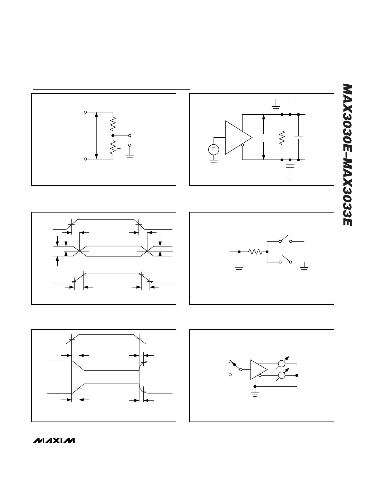
DI_+
VOD
DI_-
Вұ15kV ESD-Protected, 3.3V Quad
RS-422 Transmitters
Test Circuits and Timing Diagrams
RL
2
VOC
RL
2
CL
DO_+
DI_
VOD
RL
CL
DO_-
CL
Figure 1. Differential Driver DC Test Circuit
Figure 2. Differential Driver Propagation Delay and Transition
Time Test Circuit
3V
DI
1.5V
0V
tDPLH
tDPHL
1.5V
1/2 VO
DO_-
VO
DO_+
1/2 VO
VO
VDIFF 0V
10%
VDIFF = V (DO_+) - V (DO_-)
90%
90%
10%
-VO
tR
tF
tSKEW = |tDPLH - tDPHL|
Figure 3. Differential Driver Propagation Delay and Transition
Waveform
OUTPUT
UNDER TEST
RL
CL
S1
VCC
S2
ENABLE SIGNAL IS ONE OF THE POSSIBLE
ENABLE CONFIGURATIONS (SEE TRUTH TABLE).
Figure 4. Driver Enable/Disable Delays Test Circuit
3V
EN
1.5V
1.5V
0V
tDZL
tDLZ
VOL
1.5V OUTPUT NORMALLY LOW
VOL + 0.3V
VOH
OUTPUT NORMALLY HIGH
1.5V
0V
VOH - 0.3V
tDZH
tDHZ
ENABLE SIGNAL IS ONE OF THE POSSIBLE
ENABLE CONFIGURATIONS (SEE TRUTH TABLE).
Figure 5. Driver Enable/Disable Waveform
VCC
DO_+
A
DI
GND
A
DO_-
Figure 6. Short-Circuit Measurements
_______________________________________________________________________________________ 7
Share Link: 