MAX3814 データシートの表示(PDF) - Maxim Integrated
部品番号
コンポーネント説明
メーカー
MAX3814 Datasheet PDF : 14 Pages
| |||
DVI/HDMI TMDS FR-4 and
Cable Equalizer/Driver
CML Inputs and Outputs
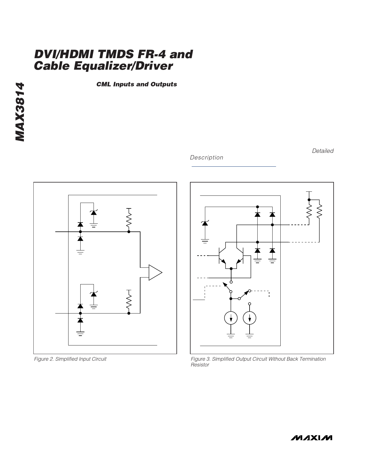
The input buffers and the output drivers are current-
mode logic (CML). See Figures 2, 3, and 4.
The input buffers consist of a 50Ω load resistor connected
to VCC and the input connected to a differential equalizer.
The output drivers are open-collector. The current in
these outputs can be adjusted to 10mA or 15mA with
the control pin LEVEL. For 10mA operation, each open-
collector output drives through a transmission line to a
50Ω pullup of the next stage, as shown in Figure 3. For
recommended 15mA operation, the two outputs are
bridged by an external 200Ω back termination resistor
that is subsequently pulled up by a 50Ω resistor of the
next stage, as shown in Figure 4. The ESD structure per-
mits signals to achieve 5.5V absolute maximum ratings,
high common-mode range, and compatibility to HDMI
testing. The back termination resistor should be placed
as close as possible to the MAX3814 in the layout.
The ESD protection for both the input and output cir-
cuitry consists of diodes connected to a transient volt-
age suppressor clamp shown as a Schottky diode in
Figures 2, 3, and 4. For more information about the
function of the suppressor clamp, refer to the Detailed
Description section of the MAX3208E data sheet
(www.maxim-ic.com/MAX3208E).
TRANSIENT VCC
SUPRESSOR
CLAMP 50Ω
IN_+
TRANSIENT
SUPRESSOR
CLAMP
VT
50Ω
50Ω
OUT_+
OUT_-
+
TRANSIENT VCC
SUPRESSOR
CLAMP 50Ω
-
EQUALIZER
ENABLE = HIGH
LEVEL = LOW
IN_-
10mA
5mA
Figure 2. Simplified Input Circuit
Figure 3. Simplified Output Circuit Without Back Termination
Resistor
8 _______________________________________________________________________________________
Share Link: 