MAX4513CSE データシートの表示(PDF) - Maxim Integrated
部品番号
コンポーネント説明
メーカー
MAX4513CSE Datasheet PDF : 17 Pages
| |||
Quad, Rail-to-Rail, Fault-Protected,
SPST Analog Switches
(TA = +25°C, unless otherwise noted.)
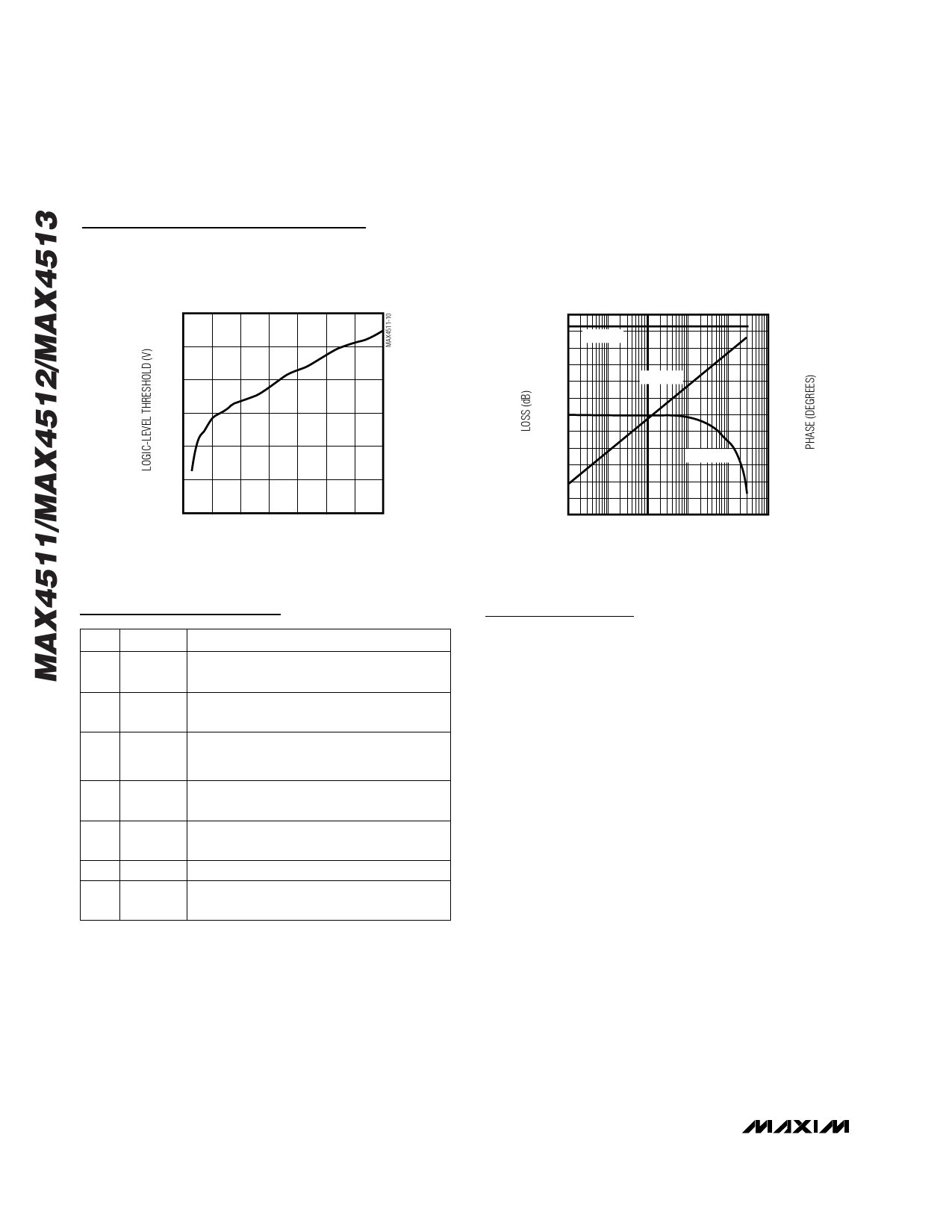
Typical Operating Characteristics (continued)
LOGIC-LEVEL THRESHOLD vs. V+
3.0
2.5
2.0
1.5
1.0
0.5
0
0 5 10 15 20 25 30 35
V+ (V)
FREQUENCY RESPONSE
0
MAX186-14A 120
-10
ON LOSS
100
-20
80
-30
60
-40
OFF LOSS
40
-50
20
-60
0
-70
-20
-80
-40
ON PHASE
-90
-60
-100
-80
-110
-100
-120
0.01 0.1
1
-120
10 100 1000
FREQUENCY (MHz)
Pin Description
PIN NAME
FUNCTION
1, 16,
9, 8
IN1–IN4
Logic Control Digital Inputs
2, 15,
10, 7
COM1–
COM4
Analog Switch Common* Terminals
3, 14,
11, 6
NO1–NO4
or
NC1–NC4
Analog Switch Fault-Protected Normally
Open* or Normally Closed* Terminals
4
V-
Negative Analog Supply Voltage Input.
Connect to GND for single-supply operation.
5
GND
Ground. Connect to digital ground. (Analog
signals have no ground reference.)
12
N.C. No Connection—not internally connected
13
V+
Positive Analog and Digital Supply-Voltage
Input. Internally connected to substrate.
*As long as the voltage on NO_ or NC_ does not exceed V+ or
V-, NO_ (or NC_) and COM_ pins are identical and interchange-
able. Either may be considered as an input or output; signals
pass equally well in either direction.
Detailed Description
Overview of Traditional
Fault-Protected Switches
The MAX4511/MAX4512/MAX4513 are fault-protected
CMOS analog switches with unusual operation and
construction. Traditional fault-protected switches are
constructed by three series FETs. This produces good
off characteristics, but fairly high on-resistance when
the signals are within about 3V of each supply rail. As
the voltage on one side of the switch approaches with-
in about 3V of either supply rail (a fault condition), the
switch impedance becomes higher, limiting the output
signal range (on the protected side of the switch) to
approximately 3V less than the appropriate polarity
supply voltage.
During a fault condition, the output current that flows
from the protected side of the switch into its load
comes from the fault source on the other side of the
switch. If the switch is open or the load is extremely
high impedance, the input current will be very low. If
the switch is on and the load is low impedance,
enough current will flow from the source to maintain the
load voltage at 3V less than the supply.
8 _______________________________________________________________________________________
Share Link: 