MAX6642 „Éá„Éľ„āŅ„ā∑„Éľ„Éą„ĀģŤ°®Á§ļÔľąPDFÔľČ - Maxim Integrated
ťÉ®ŚďĀÁē™ŚŹ∑
„ā≥„É≥„ÉĚ„Éľ„Éć„É≥„ÉąŤ™¨śėé
„É°„Éľ„āę„Éľ
MAX6642
Maxim Integrated

MAX6642 Datasheet PDF : 14 Pages
| |||
MAX6642
¬Ī1¬įC, SMBus-Compatible Remote/
Local Temperature Sensor with
Overtemperature Alarm
register was previously selected by a Write Byte
instruction. Use caution when using the shorter proto-
cols in multimaster systems, as a second master could
overwrite the command byte without informing the first
master.
Read temperature data from the read internal tempera-
ture (00h) and read external temperature (01h) regis-
ters. The temperature data format for these registers is
8 bits for each channel, with the LSB representing +1¬įC
(Table 1).
Read the additional bits from the read extended tem-
perature byte register (10h, 11h), which extends the
data to 10 bits and the resolution to +0.25¬įC per LSB
(Table 2).
When a conversion is complete, the main temperature
register and the extended temperature register are
updated.
Alarm Threshold Registers
Two registers store ALERT threshold values‚ÄĒone each
for the local and remote channels. If either measured
temperature equals or exceeds the corresponding
ALERT threshold value, the ALERT interrupt asserts
unless the ALERT bit is masked.
The power-on-reset (POR) state of the local ALERT
THIGH register is +70¬įC (0100 0110). The POR state of
the remote ALERT THIGH register is +120¬įC (0111 1000).
Diode Fault Detection
A continuity fault detector at DXP detects an open cir-
cuit on DXP, or a DXP short to VCC or GND. If an open
or short circuit exists, the external temperature register
is loaded with 1111 1111 and status bit 2 (OPEN) of the
status byte is set to 1. Immediately after POR, the status
register indicates that no fault is present. If a fault is
Table 1. Main Temperature Register
(High Byte) Data Format
TEMP (¬įC)
130.00
127.00
126.00
25
0.00
<0.00
Diode fault (short or open)
DIGITAL OUTPUT
1 000 0010
0 111 1111
0 111 1110
0 001 1001
0 000 0000
0 000 0000
1 111 1111
Table 2. Extended Resolution
Temperature Register (Low Byte)
Data Format
FRACTIONAL TEMP (¬įC)
DIGITAL OUTPUT
0.000
00XX XXXX
0.250
01XX XXXX
0.500
10XX XXXX
0.750
11XX XXXX
present upon power-up, the fault is not indicated until
the end of the first conversion. Diode faults do not set
the ALERT output.
ALERT Interrupts
The ALERT interrupt occurs when the internal or external
temperature reading exceeds a high temperature limit
(user programmed). The ALERT interrupt output signal is
latched and can be cleared only by reading the status
register after the fault condition no longer exists or by
successfully responding to the alert response address. If
A
B
C
D
EF
G
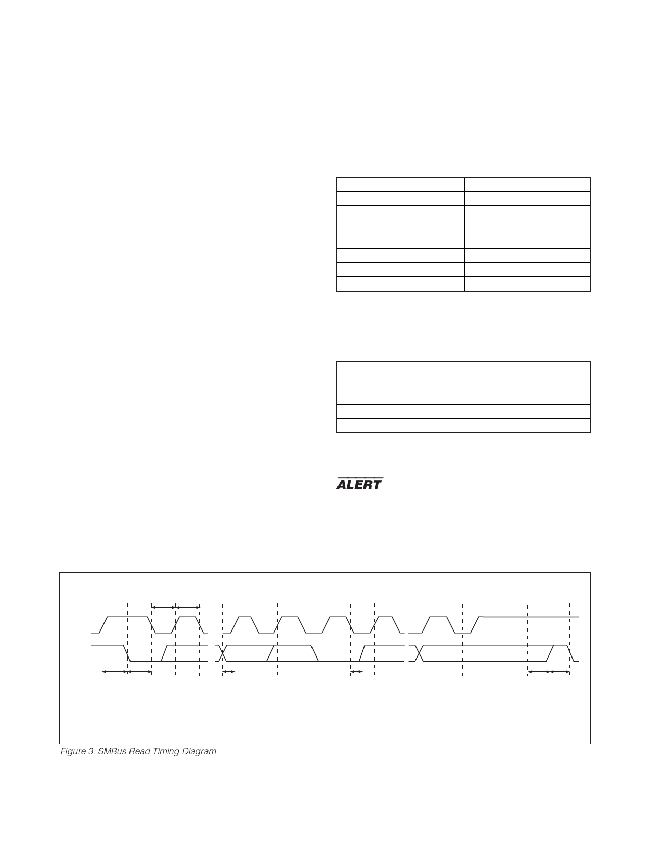
tLOW tHIGH
SMBCLK
SMBDATA
tSU:STA tHD:STA
tSU:DAT
tHD:DAT
A = START CONDITION
B = MSB OF ADDRESS CLOCKED INTO SLAVE
C = LSB OF ADDRESS CLOCKED INTO SLAVE
D = R/W BIT CLOCKED INTO SLAVE
E = SLAVE PULLS SMBDATA LINE LOW
F = ACKNOWLEDGE BIT CLOCKED INTO MASTER
G = MSB OF DATA CLOCKED INTO MASTER
H = LSB OF DATA CLOCKED INTO MASTER
Figure 3. SMBus Read Timing Diagram
www.maximintegrated.com
H
I
JK
tSU:STO tBUF
I = ACKNOWLEDGE CLOCK PULSE
J = STOP CONDITION
K = NEW START CONDITION
Maxim Integrated | 7
Share Link: