MAX7032 データシートの表示(PDF) - Maxim Integrated
部品番号
コンポーネント説明
メーカー
MAX7032
Maxim Integrated

MAX7032 Datasheet PDF : 32 Pages
| |||
Low-Cost, Crystal-Based, Programmable,
ASK/FSK Transceiver with Fractional-N PLL
AC ELECTRICAL CHARACTERISTICS (continued)
(Typical Application Circuit, 50Ω system impedance, VAVDD = VDVDD = VPAVDD = VHVIN = +2.1V to +3.6V, fRF = 300MHz to 450MHz,
TA = -40°C to +125°C, unless otherwise noted. Typical values are at VPAVDD = VAVDD = VDVDD = VHVIN = +2.7V, TA = +25°C, unless
otherwise noted.) (Note 1)
Note 1: Supply current, output power, and efficiency are greatly dependent on board layout and PAOUT match.
Note 2: 100% tested at TA = +125°C. Guaranteed by design and characterization overtemperature.
Note 3: 50% duty cycle at 10kHz ASK data (Manchester coded).
Note 4: Guaranteed by design and characterization. Not production tested.
Note 5: Time for final signal detection; does not include baseband filter settling.
Note 6: Efficiency = POUT/(VDD x IDD).
Note 7: Dependent on PCB trace capacitance.
Note 8: The oscillator register (0x05) is set to the nearest integer result of fXTAL/100kHz (see the Oscillator Frequency Register
(Address 0x05) section).
Note 9: Input impedance is measured at the LNAIN pin. Note that the impedance at 315MHz includes the 12nH inductive degenera-
tion from the LNA source to ground. The impedance at 434MHz includes a 10nH inductive degeneration connected from the
LNA source to ground. The equivalent input circuit is approximately 50Ω in series with ~ 2.2pF. The voltage conversion is
measured with the LNA input matching inductor, the degeneration inductor, and the LNA/mixer tank in place, and does not
include the IF filter insertion loss.
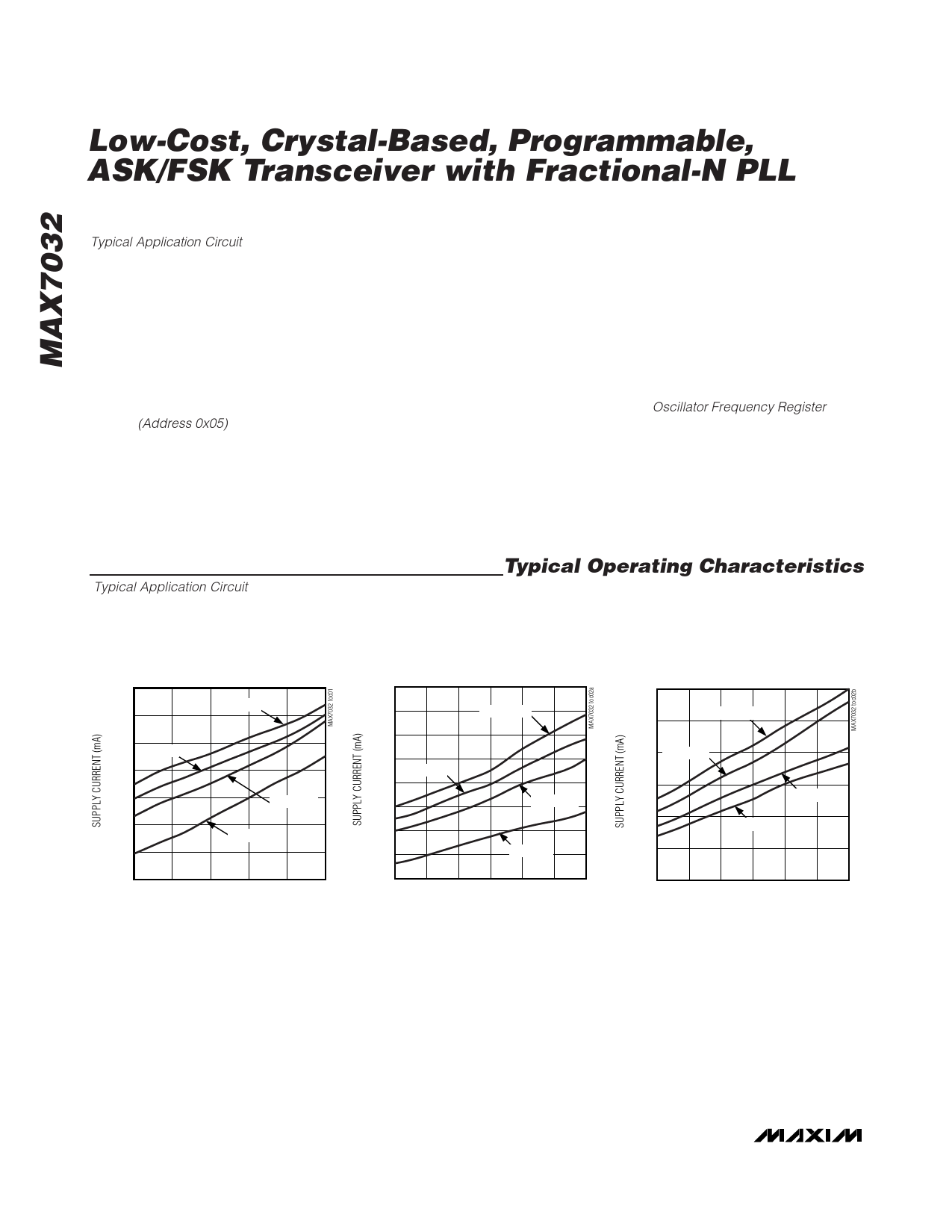
Typical Operating Characteristics
(Typical Application Circuit, VPAVDD = VAVDD = VDVDD = VHVIN = +3.0V, fRF = 433.92MHz, TA = +25°C, IF BW = 280kHz, data rate
= 4kbps Manchester encoded, frequency deviation = ±50kHz, BER = 0.2% average RF power, unless otherwise noted.)
RECEIVER
SUPPLY CURRENT vs. SUPPLY VOLTAGE
(ASK MODE)
7.0
TA = +125°C
6.8
6.6
TA = +85°C
6.4
6.2
TA = +25°C
6.0
TA = -40°C
5.8
SUPPLY CURRENT vs. RF FREQUENCY
(ASK MODE)
6.8
6.7
TA = +125°C
6.6
6.5
TA = +85°C
6.4
6.3
TA = +25°C
6.2
6.1
TA = -40°C
SUPPLY CURRENT vs. RF FREQUENCY
(FSK MODE)
7.0
6.9
TA = +125°C
6.8 TA = +85°C
6.7
6.6
6.5
TA = +25°C
TA = -40°C
5.6
2.1 2.4 2.7 3.0 3.3 3.6
SUPPLY VOLTAGE (V)
6.0
300 325 350 375 400 425 450
RF FREQUENCY (MHz)
6.4
300 325 350 375 400 425 450
RF FREQUENCY (MHz)
6 _______________________________________________________________________________________
Share Link: