MAX7034 データシートの表示(PDF) - Maxim Integrated
部品番号
コンポーネント説明
メーカー
MAX7034 Datasheet PDF : 14 Pages
| |||
MAX7034
315MHz/434MHz ASK Superheterodyne
Receiver
Peak Detector
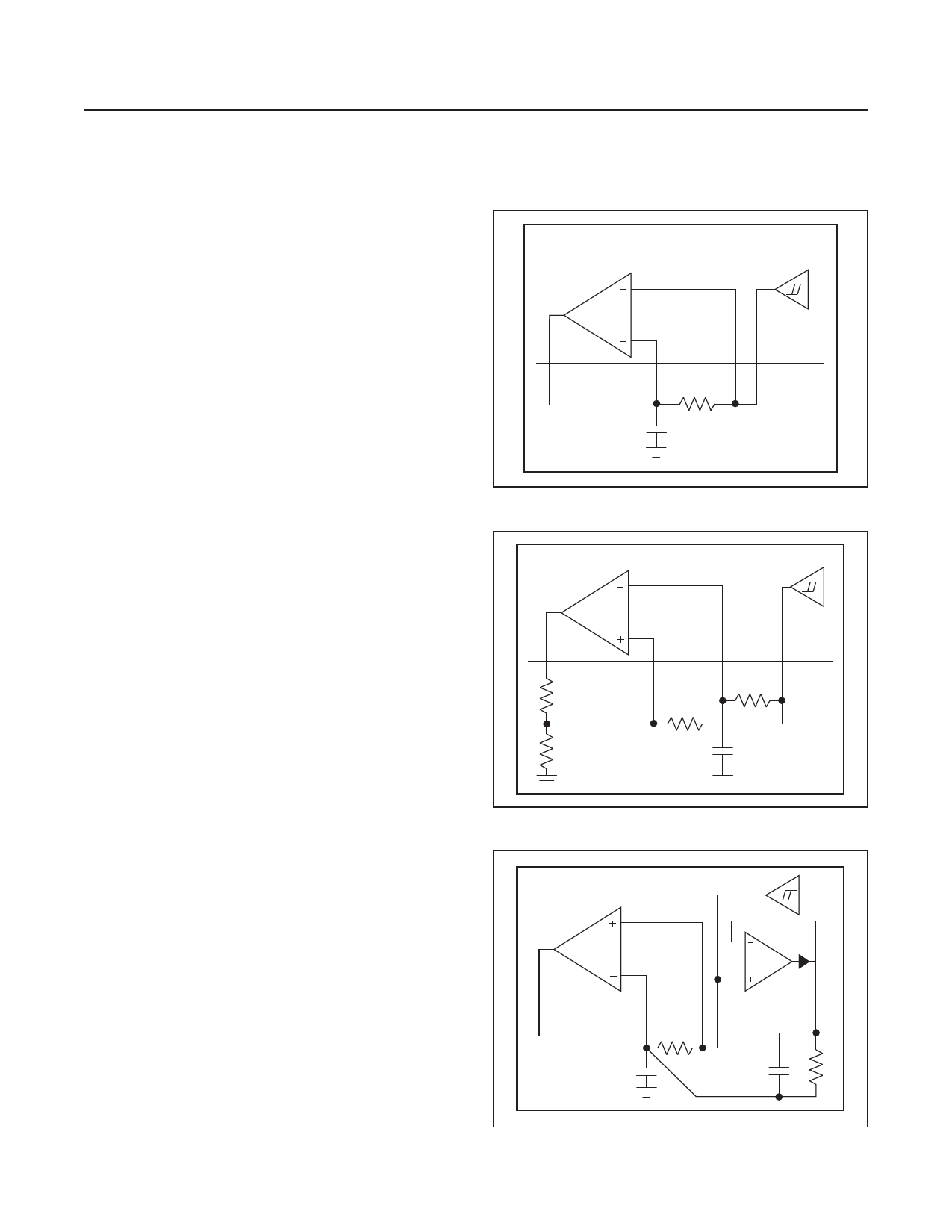
The peak-detector output (PDOUT), in conjunction with an
external RC filter, creates a DC output voltage equal to the
peak value of the data signal. The resistor provides a path
for the capacitor to discharge, allowing the peak detector
to dynamically follow peak changes of the data-filter output
voltage. For faster data slicer response, use the circuit
shown in Figure 4. For more details on hysteresis and
peak-detector applications, refer to Maxim Application Note
3671, Data Slicing Techniques for UHF ASK Receivers.
Layout Considerations
A properly designed PCB is an essential part of any RF/
microwave circuit. On high-frequency inputs and outputs,
use controlled-impedance lines and keep them as short
as possible to minimize losses and radiation. At high
frequencies, trace lengths that are on the order of λ/10 or
longer act as antennas.
Keeping the traces short also reduces parasitic induc-
tance. Generally, 1 inch of a PCB trace adds about 20nH
of parasitic inductance. The parasitic inductance can have
a dramatic effect on the effective inductance of a passive
component. For example, a 0.5 inch trace connecting a
100nH inductor adds an extra 10nH of inductance or 10%.
To reduce the parasitic inductance, use wider traces and
a solid ground or power plane below the signal traces.
Also, use low-inductance connections to ground on all
GND pins, and place decoupling capacitors close to all
power-supply pins.
Control Interface Considerations
When operating the MAX7034 with a +4.5V to +5.5V
supply voltage, the SHDN pin can be driven by a micro-
controller with either +3.0V or +5V interface logic levels.
When operating the MAX7034 with a +3.0V to +3.6V sup-
ply, only +3.0V logic from the microcontroller is allowed.
MAX7034
DATA
SLICER
25
DATAOUT
20
23
19
DSN
DSP
DFO
R1
C8
Figure 2. Generating Data Slicer Threshold
DATA
SLICER
MAX7034
25
DATAOUT
R2
23
20
19
DSP
DSN
R1
DFO
R3
R* *OPTIONAL
C8
Figure 3. Generating Data Slicer Hysteresis
MAX7034
DATA
SLICER
25
DATAOUT
20
23 19
DSN
DSP DFO
25kΩ
47nF
26
PDOUT
www.maximintegrated.com
Figure 4. Using PDOUT for Faster Startup
Maxim Integrated │ 11
Share Link: 