MAX9541 データシートの表示(PDF) - Maxim Integrated
部品番号
コンポーネント説明
メーカー
MAX9541 Datasheet PDF : 17 Pages
| |||
MAX9541/MAX9542
Quadruple, 2:1, Mux Amplifiers for
Standard-Definition and VGA Signals
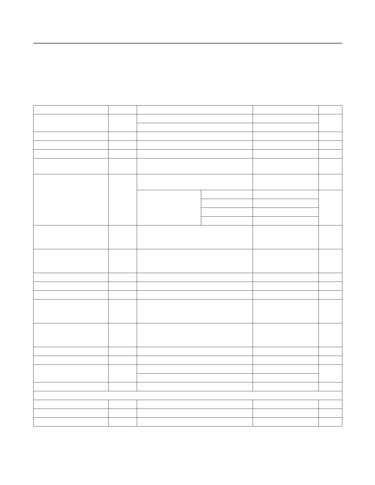
Electrical Characteristics (continued)
(VDD = 3.3V, VGND = 0, SHDN = VDD, A/B = VDD, RL = 150Ω to GND, TA = TMIN to TMAX, unless otherwise noted. Typical values
are at TA = +25°C.) (Note 1)
PARAMETER
SYMBOL
CONDITIONS
MIN TYP MAX UNITS
Power-Supply Rejection Ratio
2.7V ≤ VDD ≤ 3.6V
f = 100kHz, 100mVP-P
48
64
dB
20
Small-Signal Bandwidth
VOUT = 100mVP-P (MAX9542 only)
27
MHz
Large-Signal Bandwidth
VOUT = 2VP-P (MAX9542 only)
15
MHz
Slew Rate
MAX9542 only
65
V/µs
Settling Time
Settled to within 0.1% of final value
(MAX9542 only)
75
ns
VOUT = 2VP-P, reference frequency is 100kHz,
±1dB passband flatness (MAX9541 only)
9.5
MHz
Standard-Definition
Reconstruction Filter
VOUT = 2VP-P, reference
frequency is 100kHz
(MAX9541 only)
f = 5.5MHz
f = 9.5MHz
f = 10MHz
f = 27MHz
0.1
-1
dB
-3
-47
Differential Gain
5-step modulated staircase of 129mV step size
DG
and 286mV peak-to-peak subcarrier amplitude,
0.4
%
f = 4.43MHz
Differential Phase
5-step modulated staircase of 129mV step size
DP
and 286mV peak-to-peak subcarrier amplitude,
0.45
deg
f = 4.43MHz
Group-Delay Distortion
Peak Signal to RMS Noise
2T Pulse Response
100kHz ≤ f ≤ 5MHz, outputs are 2VP-P
100kHz ≤ f ≤ 5MHz
2T = 200ns
9
ns
71
dB
0.2
K%
2T Bar Response
2T = 200ns; bar time is 18ms; the beginning
2.5%, and the ending 2.5% of the bar time is
ignored
0.2
K%
2T Pulse-to-Bar K Rating
2T = 200ns; bar time is 18ms; the beginning
2.5%, and the ending 2.5% of the bar time is
ignored
0.3
K%
Nonlinearity
5-step staircase
0.1
%
Output Impedance
f = 5.5MHz
8.07
Ω
All-Hostile Crosstalk
f = 15kHz
f = 4.43MHz
-82
dB
-78
Output-to-Input Crosstalk
f = 30MHz
-68
dB
LOGIC SIGNALS (TV_SEL, VCR_SEL, SHDN)
Logic-Low Threshold
VIL
0.3 x VDD
V
Logic-High Threshold
VIH
0.7 x VDD
V
Logic-Input Current
IIN
10
µA
Note 1: All devices are 100% production tested at TA = +25°C. Specifications over temperature limits are guaranteed by design.
Note 2: Voltage gain (AV) is a two-point measurement in which the output-voltage swing is divided by the input-voltage swing.
www.maximintegrated.com
Maxim Integrated │ 3
Share Link: 