MT46V128M4TG-8 データシートの表示(PDF) - Micron Technology
部品番号
コンポーネント説明
メーカー
MT46V128M4TG-8 Datasheet PDF : 68 Pages
| |||
ADVANCE
512Mb: x4, x8, x16
DDR SDRAM
EXTENDED MODE REGISTER
The extended mode register controls functions be-
yond those controlled by the mode register; these ad-
ditional functions are DLL enable/disable and
output drive strength. These functions are controlled
via the bits shown in Figure 3. The extended mode
register is programmed via the LOAD MODE REGIS-
TER command to the mode register (with BA0 = 1 and
BA1 = 0) and will retain the stored information until it is
programmed again or the device loses power. The en-
abling of the DLL should always be followed by a LOAD
MODE REGISTER command to the mode register (BA0/
BA1 both LOW) to reset the DLL.
The extended mode register must be loaded when
all banks are idle and no bursts are in progress, and the
controller must wait the specified time before initiat-
ing any subsequent operation. Violating either of these
requirements could result in unspecified operation.
Output Drive Strength
The normal drive strength for all outputs are speci-
fied to be SSTL2, Class II. The x16 supports an option
for reduced drive. This option is intended for the sup-
port of the lighter load and/or point-to-point environ-
ments. The selection of the reduced drive strength will
alter the DQs and DQSs from SSTL2, Class II drive
strength to a reduced drive strength, which is approxi-
mately 54% of the SSTL2, Class II drive strength.
The Micron (32Meg x16) device supports a
programmable drive strength option.
DLL Enable/Disable
The DLL must be enabled for normal operation.
DLL enable is required during power-up initialization
and upon returning to normal operation after having
disabled the DLL for the purpose of debug or evalua-
tion. (When the device exits self refresh mode, the DLL
is enabled automatically.) Any time the DLL is enabled,
200 clock cycles must occur before a READ command
can be issued.
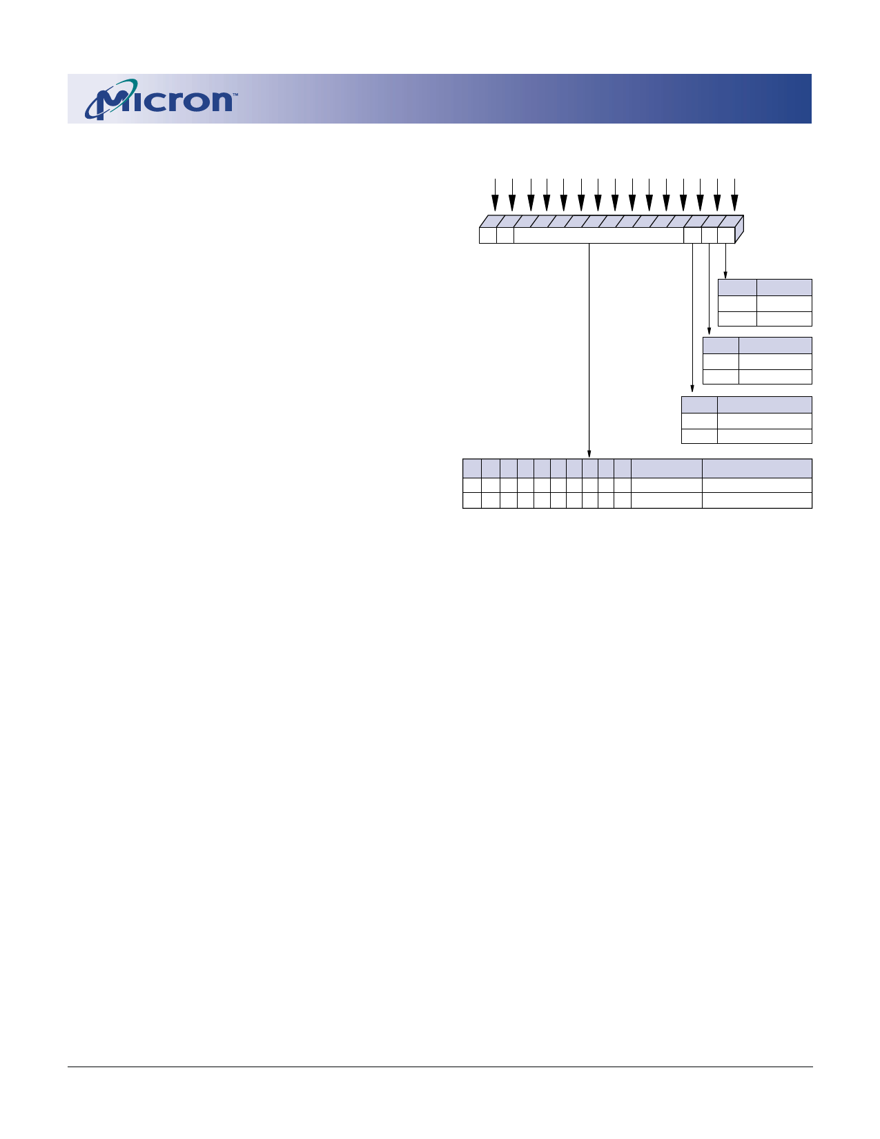
BA1 BA0 A12 A11 A10 A9 A8 A7 A6 A5 A4 A3 A2 A1 A0 Address Bus
14 13 12 11 10 9 8 7 6 5 4 3 2 1 0 Extended Mode
01 11
Operating Mode
QFC# DS DLL Register (Ex)
E0
DLL
0
Enable
1
Disable
E12 Drive Strength
0
Normal
1
Reduced
E23
QFC# Function
0
Disabled
–
Reserved
E12 E11 E10 E9 E8 E7 E6 E5 E4 E3
0 0 0 0 0 0 00 0 0
– – – – – – –– – –
E2, E1, E0
Valid
–
Operating Mode
Reserved
Reserved
NOTE: 1. E14 and E13 (BA0 and BA1) must be “1, 0” to select the
Extended Mode Register (vs. the base Mode Register).
2. The reduced drive strength option is not supported on the x4
and x8 versions, and is only available on the x16 version.
3. The QFC# option is not supported.
Figure 3
Extended Mode Register Definition
512Mb: x4, x8, x16 DDR SDRAM
512Mx4x8x16DDR_B.p65 – Rev. B; Pub 4/01
12
Micron Technology, Inc., reserves the right to change products or specifications without notice.
©2001, Micron Technology, Inc.
Share Link: 