TC620HCOA データシートの表示(PDF) - TelCom Semiconductor, Inc
部品番号
コンポーネント説明
メーカー
TC620HCOA Datasheet PDF : 6 Pages
| |||
5V, DUAL TRIP POINT
TEMPERATURE SENSORS
1
TC620
TC621
DETAILED DESCRIPTION
The TC620/621 consists of a positive temperature coef-
ficient (PTC) temperature sensor, and a dual threshold
detector. Temperature setpoint programming is easily ac-
complished with external programming resistors from the
HIGH SET and LOW SET inputs to VDD. The HIGH LIMIT
and LOW LIMIT outputs remain low as long as measured
temperature is below setpoint values. As measured tem-
perature increases, the LOW LIMIT output is driven high
when temperature equals the LOW SET setpoint (±3°C
max). If temperature continues to climb, the HIGH LIMIT
output is driven high when temperature equals the HIGH
SET setpoint (Figure 1). The CONTROL (hysteresis) output
is latched in its active state at the temperature specified by
the HIGH SET resistor. CONTROL is maintained active until
temperature falls to the value specified by the LOW SET
resistor.
HIGH SET POINT
LOW SET POINT
LOW LIMIT OUTPUT
HIGH LIMIT OUTPUT
CONTROL OUTPUT (COOL OPTION)
CONTROL OUTPUT (HEAT OPTION)
TEMPERATURE
Figure 1: TC620/621 Input vs. Output Logic
Programming The TC620
The resistor values to achieve the desired trip-point
temperatures on HIGH SET and LOW SET are calculated
using EQUATION 1 below:
RTRIP = 0.5997 x T 2.1312
Where: Rtrip = Programming resistor in Ohms
T = The desired trip point temperature
in degrees Kelvin
Equation 1.
For example, a 50°C setting on either the HIGH SET or
LOW SET input is calculated using Equation 1 as follows:
Rset = 0.5997 x ((50 + 273.15)2.1312) = 133.6k Ω
Care must be taken to ensure the LOW SET program-
2 ming resistor is a smaller value than the HIGH SET program-
ming resistor. Failure to do this will result in erroneous
operation of the CONTROL output.
Care must also be taken to ensure the LOW SET
temperature setting is at least 5°C lower than the HIGH SET
temperature setting. That is:
LOW SET ≤ HIGH SET – 5°C
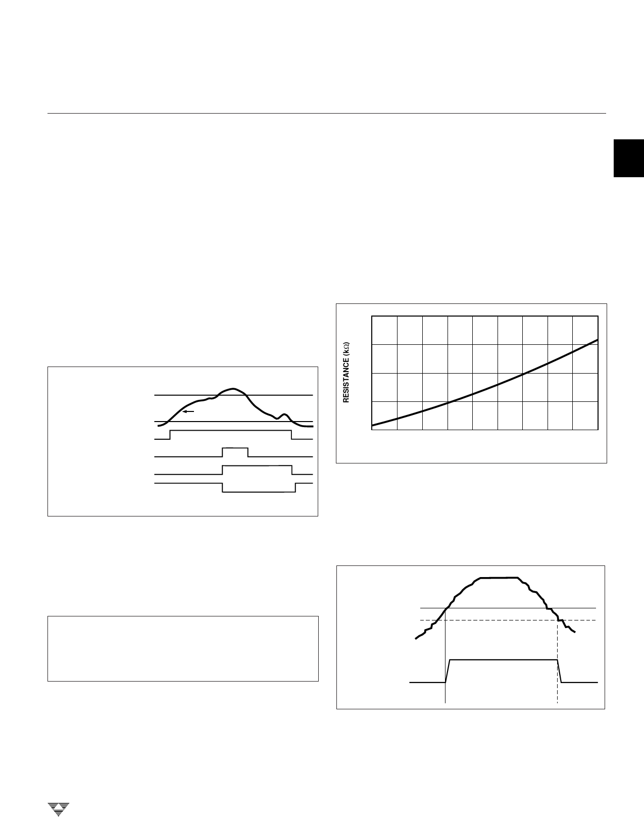
3 The nomograph of Figure 2 can help the user obtain an
estimate of the external resistor values required for the
desired LOW SET and HIGH SET trip points.
250
200
4
150
100
50
-55 -35 -15
5 25 45 65
TEMPERATURE (°C)
85 105 125
Figure 2. TC620 Sense Resistors vs. Trip Temperature
5
Built-in Hysteresis
To prevent output "chattering" when measured tem-
perature is at (or near) the programmed trip point values, the
LOW SET and HIGH SET inputs each have built-in hyster-
esis of – 2°C below the programmed settings (Figure 3).
6
SET POINT
(SET POINT – 2°C)
HIGH LIMIT
7
or LOW LIMIT
Output
Figure 3: Built-in Hysteresis on Low Limit and High Limit Outputs
As shown, the outputs remain in their active state
(hysteresis) until temperature falls an additional 2°C below
the user's setting.
8
TELCOM SEMICONDUCTOR, INC.
2-17
Share Link: 