UEI15 データシートの表示(PDF) - Murata Manufacturing
部品番号
コンポーネント説明
メーカー
UEI15 Datasheet PDF : 13 Pages
| |||
UEI15 Series
Isolated Wide Input Range 15-Watt DC/DC Converters
Output Current Limiting
As soon as the output current increases to approximately 125% to 150% of
its maximum rated value, the DC/DC converter will enter a current-limiting
mode. The output voltage will decrease proportionally with increases in output
current, thereby maintaining a somewhat constant power output. This is com-
monly referred to as power limiting.
Current limiting inception is defined as the point at which full power falls
below the rated tolerance. See the Performance/Functional Specifications. Note
particularly that the output current may briefly rise above its rated value. This
enhances reliability and continued operation of your application. If the output
current is too high, the converter will enter the short circuit condition.
Output Short Circuit Condition
When a converter is in current-limit mode, the output voltage will drop as
the output current demand increases. If the output voltage drops too low, the
magnetically coupled voltage used to develop primary side voltages will also
drop, thereby shutting down the PWM controller. Following a time-out period,
the PWM will restart, causing the output voltage to begin ramping up to its ap-
propriate value. If the short-circuit condition persists, another shutdown cycle
will initiate. This on/off cycling is called “hiccup mode”. The hiccup cycling
reduces the average output current, thereby preventing excessive internal
temperatures. A short circuit can be tolerated indefinitely.
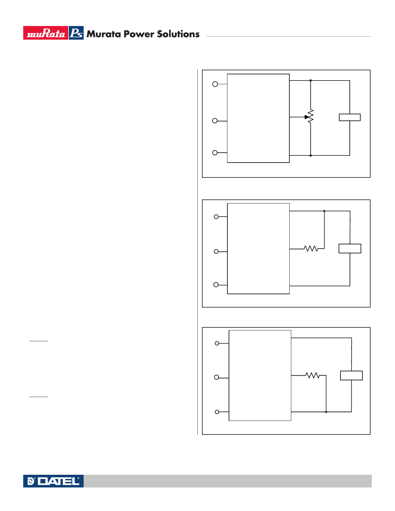
Trimming the Output Voltage
The Trim input to the converter allows the user to adjust the output voltage
over the rated trim range (please refer to the Specifications). In the trim equa-
tions and circuit diagrams that follow, trim adjustments use either a trimpot or
a single fixed resistor connected between the Trim input and either the positive
or negative output terminals. (On some converters, an external user-supplied
precision DC voltage may also be used for trimming). Trimming resistors should
have a low temperature coefficient (±100 ppm/deg.C or less) and be mounted
close to the converter. Keep leads short. If the trim function is not used, leave
the trim unconnected. With no trim, the converter will exhibit its specified
output voltage accuracy.
There are two CAUTIONs to be aware for the Trim input:
CAUTION: To avoid unplanned power down cycles, do not exceed EITHER the
maximum output voltage OR the maximum output power when setting the trim.
Be particularly careful with a trimpot. If the output voltage is excessive, the
OVP circuit may inadvertantly shut down the converter. If the maximum power
is exceeded, the converter may enter current limiting. If the power is exceeded
for an extended period, the converter may overheat and encounter overtem-
perature shut down.
CAUTION: Be careful of external electrical noise. The Trim input is a senstive
input to the converter’s feedback control loop. Excessive electrical noise may
cause instability or oscillation. Keep external connections short to the Trim
input. Use shielding if needed.
−INPUT
+OUTPUT
ON/OFF
TRIM
CONTROL
7 5-22
TURNS
LOAD
+INPUT
−OUTPUT
Figure 4 – Trim adjustments using a trimpot
−INPUT
+OUTPUT
ON/OFF
CONTROL
TRIM
RTRIM DOWN
LOAD
+INPUT
−OUTPUT
Figure 5 – Trim adjustments to decrease Output Voltage using a Fixed Resistor
−INPUT
+OUTPUT
ON/OFF
CONTROL
TRIM
R TRIM UP
LOAD
+INPUT
−OUTPUT
Figure 6 – Trim adjustments to increase Output Voltage using a Fixed Resistor
www.murata-ps.com
Technical enquiries email: sales@murata-ps.com, tel: +1 508 339 3000
MDC_UEI15W.B21 Page 8 of 13
Share Link: 