AN728 データシートの表示(PDF) - Vishay Semiconductors
部品番号
コンポーネント説明
メーカー
AN728
Vishay Semiconductors

AN728 Datasheet PDF : 10 Pages
| |||
AN728
Vishay Siliconix
110/220 VAC
TE1
R
TE2
110/220 VAC
Needed Only
for Long Loops
Battery Voltage
(48- to 60-V Typ.)
TE1
S
Si9113
U
U
dc-dc Converter
RG
NT
Central
Office
Switch
TA
Customer
Premises
Transmission
Line
Local Telephone
Exchange
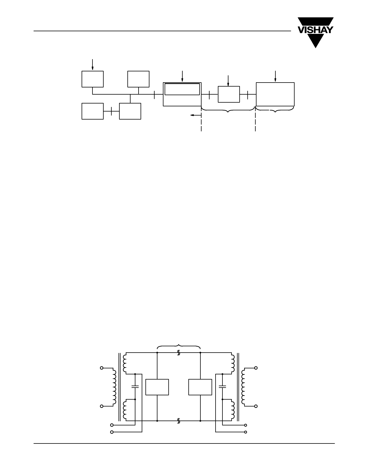
FIGURE 12. ISDN Functional Groups and Reference Points
ISDN REFERENCE MODEL
Figure 12 is a reference model and shows how various
functional groups are connected together to gain access to the
ISDN network. The points which divide the functional groups
are referred to as reference (interface) points, and will typically
correspond to a particular physical interface connecting two
pieces of equipment.
The S-interface is also known as the user-network interface
(UNI) as it represents the common interface at which terminal
equipment (TE) can be connected to the ISDN. The functions
are:
D Terminal equipment, type 1 (TE1): examples are
telephones, fax machines and videophones which can be
directly connected to the S-interface and have the ability
to establish and terminate a call.
D Terminal equipment, type 2 (TE2): examples are analog
phones, computers, and communications terminal
equipment. TE2’s do not have an ISDN UNI and rely on a
terminal adapter (TA) to operate as the TE1 functional
group in order to connect to S-interface.
D Terminal adapter (TA): adapts a non-ISDN terminal to the
ISDN. It will contain functions which include layer 1
(physical layer) and higher layers (including call
processing) of the OSI reference model.
D Network Termination, type 1 (NT1): It marks the point at
which the public network ends and the customer premise
begins. NT1 equipment provides a conversion at the
physical layer between S-interface that runs inside a
customer premise and the subscriber loop cable at the
U-interface that connects to the local exchange. An
important function of NT1 is to feed power to the TE
either from the local mains supply or from the network as
a backup when the mains power fails.
D Network Termination, type 2 (NT2): Unlike NT1
equipment that provides only a physical translation
between S- and U-interfaces, NT2 equipment may also
incorporate more complex functions such as switching
and multiplexing. A private branch exchange (PBX),
inside customer premises, routes calls and provides its
users with internal voice services, as well as access to
external lines connected to the ISDN. Such an
ISDN-based PBX belongs to the NT2.
Line Termination (LT): LT marks the end of the ISDN subscriber
loop. It is typically located within the local exchange equipment
as a line card containing the terminations for a number of
subscriber lines. If the distance between LT and NT is greater
than that supported by the U-interface, a signal regenerator
(RG) is required.
U-Interface
To NT
Protection
Circuit
Protection
Circuit
To Local
Exchange
dc Voltage
Sink
www.vishay.com S FaxBack 408-970-5600
8
dc Voltage
Source
FIGURE 13. Power Feed Configuration at the U-Interface
Document Number: 71120
29-Feb-00
Share Link: