AN728 データシートの表示(PDF) - Vishay Semiconductors
部品番号
コンポーネント説明
メーカー
AN728
Vishay Semiconductors

AN728 Datasheet PDF : 10 Pages
| |||
AN728
Vishay Siliconix
POWER FEEDING TO NT
Figure 13 illustrates the method used to provide a power feed
across the U-interface from the local exchange to the NT1. The
two conductors on the U-interface are separated with a
capacitor to allow a dc voltage to be applied and to enable ac
signals to pass without attenuation. Protection circuitry is
added as needed.
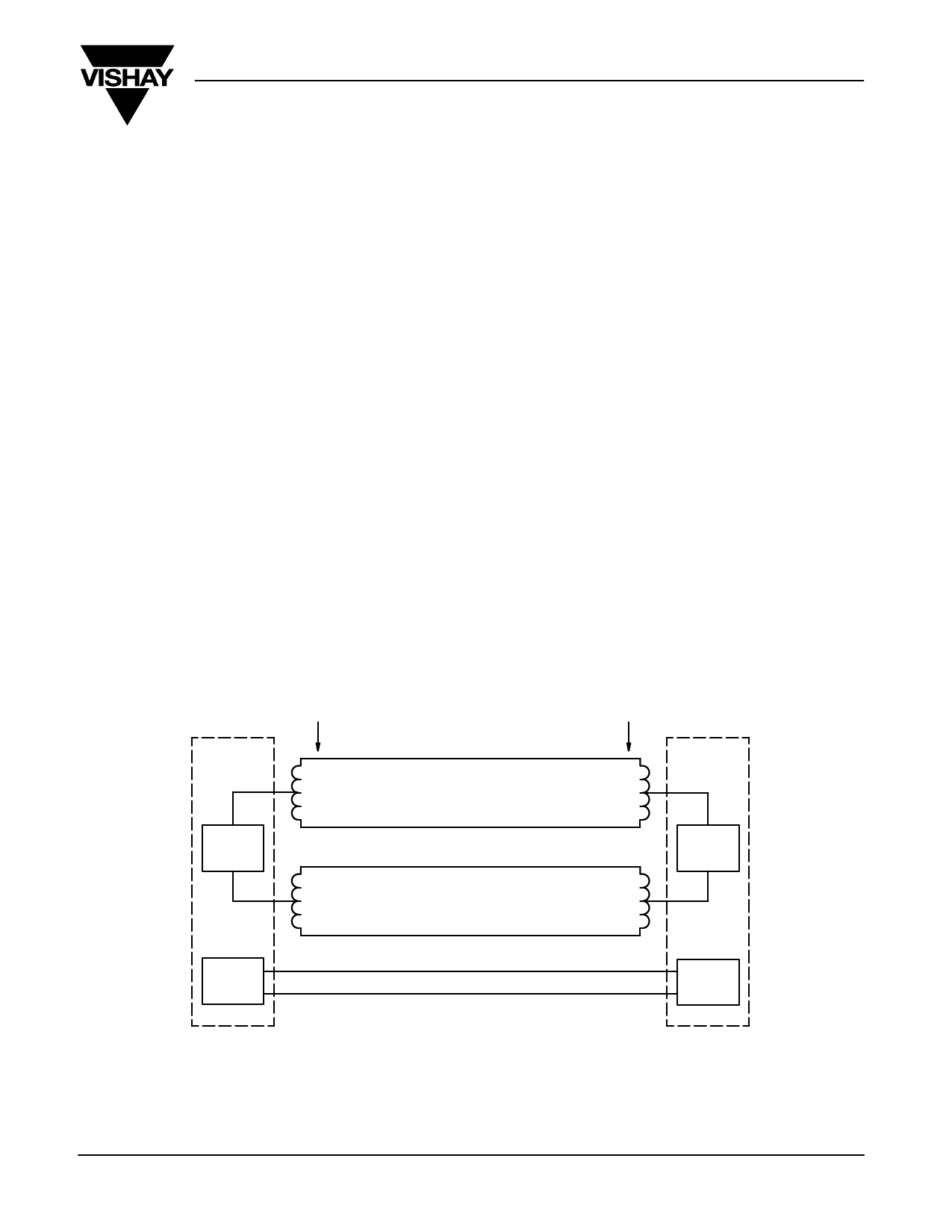
POWER FEEDING TO TE
Power is fed from NT1 to TE in two configurations (Figure 14).
In the first configuration, power source 1 (PS1) feeds power to
the transformer at the NT, where the signal is injected. The
signal is then recovered from the transformer at the TE. A dc-dc
converter is used to power the TE circuitry.
Under normal conditions, the S-interface may be powered
locally from the NT1 using mains or batteries, and is backed up
with remote power from the network under emergency power
conditions where the local power source fails.
When active, the NT1 must consume no more than 500 mW
of power from the network, and in a deactivated state must
consume no more than 120 mW. Under emergency power
conditions when NT1 is expected to also power the user’s
designated TE across the S-interface, then the power
consumption of an active NT1 is allowed to rise to a maximum
of 1.1 W (although this varies between different ISDNs due to
different safety requirements and subscriber loop
configurations). The minimum voltage required for correct
operation at the NT1 is 28 V, while the feed voltage at the
exchange may vary among networks from 51 V to 115 V.
In the second configuration, power source 2 (PS2) feeds
power through a separate pair of conductors within the
S-cable. These conductors are independent of the transmit
and receive signal conductors. PS2 is capable of delivering
higher levels of power to TEs. Power feeding designs and
configurations vary among network operators and between
different countries and regions.
Table 1 shows how a dc-dc converter feeds power to the
S-interface on an NT1 board. Under normal conditions, the TE
power comes from an ac-dc converter via a relay. In a mains
failure condition, the relay switches the connection over to the
dc-dc converter and polarity reverses. Such polarity reversal
causes the TE to operate in restricted mode to minimize power
drawn from U-interface.
Signal
Transformer
TE
+
TX
–
Power
Source 1
RX
Power
Source 2
c
d
Power Feed
e
f
g
h
Power Feed
Signal
Transformer
NT
RX
+
Power
Source 1
+
TX
–
–
Power
Source 2
FIGURE 14. Power Feed Configurations at the S-Interface
Document Number: 71120
29-Feb-00
www.vishay.com S FaxBack 408-970-5600
9
Share Link: