1DDD356AA-K01 データシートの表示(PDF) - Unspecified
部品番号
コンポーネント説明
メーカー
1DDD356AA-K01 Datasheet PDF : 12 Pages
| |||
Designing With D356A
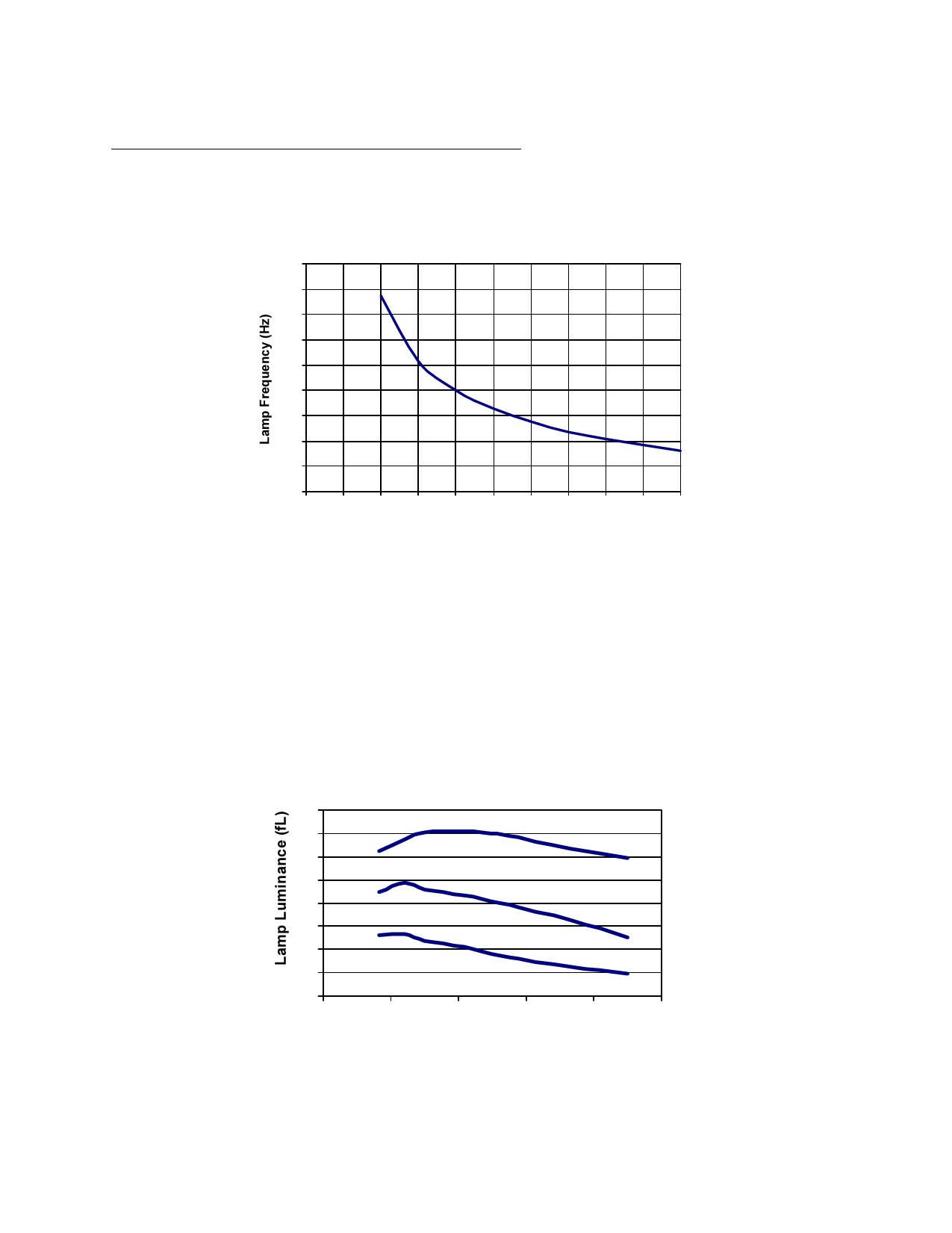
I. Lamp Frequency Capacitor (CLF) Selection
Selecting the appropriate value of capacitor for the low frequency oscillator (CLF) will set the output frequency of the
D356A inverter. Figure 1 graphically represents the inversely proportional relationship between the CLF capacitor
value and the oscillator frequency. In this example at V+ = 3.0V, LF=1600 nF-Hz/CLF.
900
800
700
600
500
400
300
200
100
0
0 1 2 3 4 5 6 7 8 9 10
CLF (nF)
Figure 1: Typical Lamp Frequency vs. CLF Capacitor
Alternatively, the lamp frequency may also be controlled with an external clock signal with a 50% duty cycle. The
output lamp frequency will be the same frequency as the input clock signal. For example, if a 250Hz input clock signal
is used, the resulting lamp frequency will be 250Hz. The clock signal input voltage should not exceed V+.
The selection of the CLF value can also affect the brightness of the EL lamp because of its control of the lamp
frequency (LF). Although input voltage and lamp size can change EL lamp frequency as well, LF mainly depends on
the CLF value selected or the frequency of the input clock signal to CLF. The luminance of various sizes of Durel 3
Blue-green EL lamp driven by a D356A at V+ = 3.0V using the same inductor value is shown in Figure 2 with respect
to lamp frequency.
8
7
6
5
2in2 EL Lamp
4
4in2 EL Lamp
3
2
6in2 EL Lamp
1
0
0
200
400
600
800 1000
Lamp Frequency (Hz)
Figure 2: Typical Lamp Luminance vs. Lamp Frequency
6
Share Link: 