HT45FM03B データシートの表示(PDF) - Holtek Semiconductor
部品番号
コンポーネント説明
メーカー
HT45FM03B Datasheet PDF : 83 Pages
| |||
Program Counter
During program execution, the Program Counter is used
to keep track of the address of the next instruction to be
executed. It is automatically incremented by one each
time an instruction is executed except for instructions,
such as ²JMP² or ²CALL², that demand a jump to a
non-consecutive Program Memory address. It must be
noted that only the lower 8 bits, known as the Program
Counter Low Register, are directly addressable by user.
When executing instructions requiring jumps to
non-consecutive addresses such as a jump instruction,
a subroutine call, interrupt or reset, etc., the
microcontroller manages program control by loading the
required address into the Program Counter. For condi-
tional skip instructions, once the condition has been
met, the next instruction, which has already been
fetched during the present instruction execution, is dis-
carded and a dummy cycle takes its place while the cor-
rect instruction is obtained.
The lower byte of the Program Counter, known as the
Program Counter Low register or PCL, is available for
program control and is a readable and writable register.
By transferring data directly into this register, a short
program jump can be executed directly, however, as
only this low byte is available for manipulation, the
jumps are limited to the present page of memory, that is
256 locations. When such program jumps are executed
it should also be noted that a dummy cycle will be in-
serted.
The lower byte of the Program Counter is fully accessi-
ble under program control. Manipulating the PCL might
cause program branching, so an extra cycle is needed
to pre-fetch. Further information on the PCL register can
be found in the Special Function Register section.
HT45FM03B
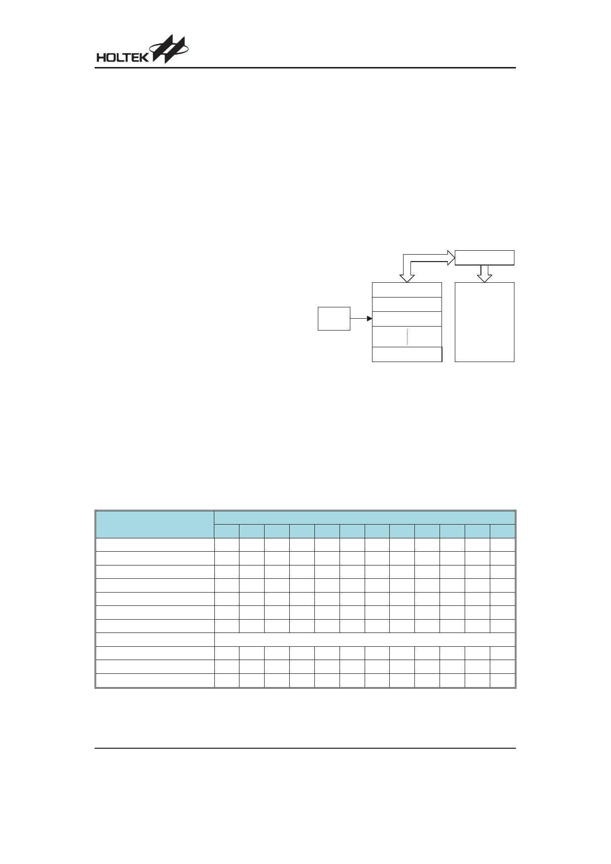
Stack
This is a special part of the memory which is used to
save the contents of the Program Counter only. The
stack has 8 levels and is neither part of the data nor part
of the program space, and can neither be read from nor
writeable. The activated level is indexed by the Stack
Pointer, SP, and is neither readable nor writeable. At a
subroutine call or interrupt acknowledge signal, the con-
tents of the Program Counter are pushed onto the stack.
At the end of a subroutine or an interrupt routine, sig-
naled by a return instruction, RET or RETI, the Program
Counter is restored to its previous value from the stack.
After a device reset, the Stack Pointer will point to the
top of the stack.
P ro g ra m C o u n te r
T o p o f S ta c k
S ta c k
P o in te r
S ta c k L e v e l 1
S ta c k L e v e l 2
S ta c k L e v e l 3
P ro g ra m
M e m o ry
B o tto m o f S ta c k
S ta c k L e v e l 8
If the stack is full and an enabled interrupt takes place,
the interrupt request flag will be recorded but the ac-
knowledge signal will be inhibited. When the Stack
Pointer is decremented, by RET or RETI, the interrupt
will be serviced. This feature prevents stack overflow al-
lowing the programmer to use the structure more easily.
However, when the stack is full, a CALL subroutine in-
struction can still be executed which will result in a stack
overflow. Precautions should be taken to avoid such
cases which might cause unpredictable program
branching.
Mode
Program Counter Bits
b11 b10 b9 b8 b7 b6 b5 b4 b3 b2 b1 b0
Initial Reset
000000000000
Analog Comparator Interrupt
000000000100
External Interrupt 0
000000001000
Multi-function Interrupt
000000001100
PWM Interrupt
000000010000
Timer/Event Counter 0 Overflow 0 0 0 0 0 0 0 1 0 1 0 0
Timer/Event Counter 1 Overflow 0 0 0 0 0 0 0 1 1 0 0 0
Skip
Program Counter + 2
Loading PCL
PC11 PC10 PC9 PC8 @7 @6 @5 @4 @3 @2 @1 @0
Jump, Call Branch
#11 #10 #9 #8 #7 #6 #5 #4 #3 #2 #1 #0
Return from Subroutine
S11 S10 S9 S8 S7 S6 S5 S4 S3 S2 S1 S0
Program Counter
Note: PC11~PC8: Current Program Counter bits
#11~#0: Instruction code address bits
@7~@0: PCL bits
S11~S0: Stack register bits
Rev. 1.10
11
May 7, 2010
Share Link: 