TEA1761T データシートの表示(PDF) - NXP Semiconductors.
部品番号
コンポーネント説明
メーカー
TEA1761T Datasheet PDF : 13 Pages
| |||
NXP Semiconductors
TEA1761T
GreenChip synchronous rectifier controller
2600
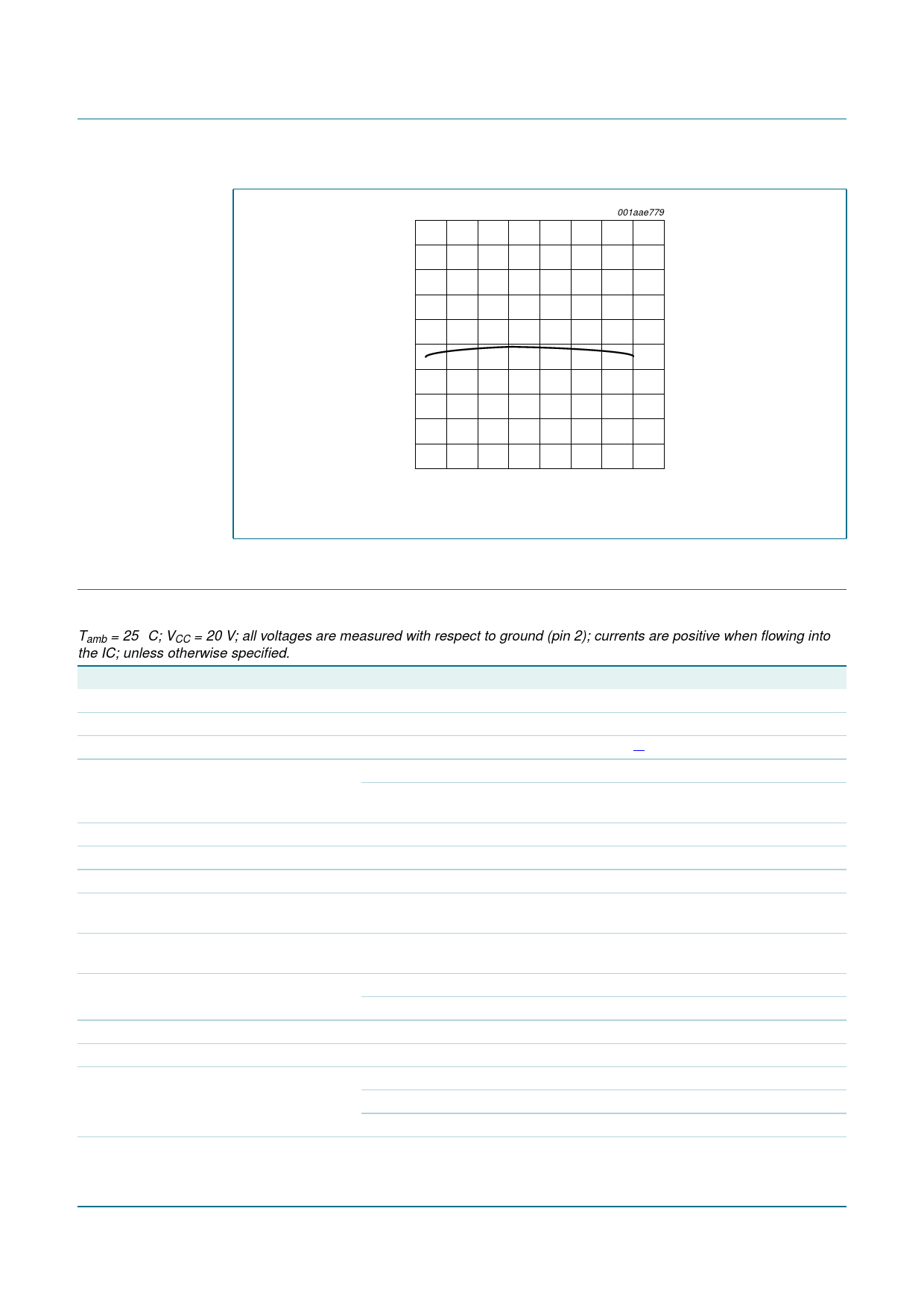
regulated
VSENSE
voltage
(mV)
2520
001aae779
2480
2440
2400
−50
0
50
100
150
junction temperature (°C)
Fig 4. Typical regulated VSENSE voltage versus junction temperature
10. Characteristics
Table 5. Characteristics
Tamb = 25 °C; VCC = 20 V; all voltages are measured with respect to ground (pin 2); currents are positive when flowing into
the IC; unless otherwise specified.
Symbol
Parameter
Conditions
Min Typ Max Unit
Supply voltage management (pin VCC)
Vstartup
start-up voltage
Vhys
hysteresis voltage
ICC(oper)
operating supply current
VCC = 8 V (VCC < Vstartup)
under normal operation; no load on
pin DRIVER
8.35 8.6
[1]
0.5
-
1
-
1.4
8.85 V
V
-
mA
-
mA
Synchronous rectification sense input (pin SRSENSE)
Vact(drv)
Vreg(drv)
Vdeact(drv)
driver activation voltage
driver regulation voltage
driver deactivation
voltage
−340 −310 −280 mV
−65 −55 −45 mV
−12
mV
td(act)(drv)
driver activation delay
time
-
125 -
ns
tact(sr)(min)
minimum synchronous Short time
rectification active time Long time
1.5 2
2.5 µs
1.7 2.2 2.7 µs
Driver (pin DRIVER)
Isource
Isink
source current
sink current
VCC = 15 V; voltage on pin DRIVER = 2 V
VCC = 15 V;
voltage on pin DRIVER = 2 V
−0.3 −0.25 −0.2 A
1
1.4 -
A
voltage on pin DRIVER = 9.5 V
2.2 2.7 -
A
Vo(max)
maximum output voltage VCC = 15 V
-
10 12 V
TEA1761T_2
Product data sheet
Rev. 02 — 25 April 2007
© NXP B.V. 2007. All rights reserved.
7 of 13
Share Link: 