TEA1761T データシートの表示(PDF) - NXP Semiconductors.
部品番号
コンポーネント説明
メーカー
TEA1761T Datasheet PDF : 13 Pages
| |||
NXP Semiconductors
TEA1761T
GreenChip synchronous rectifier controller
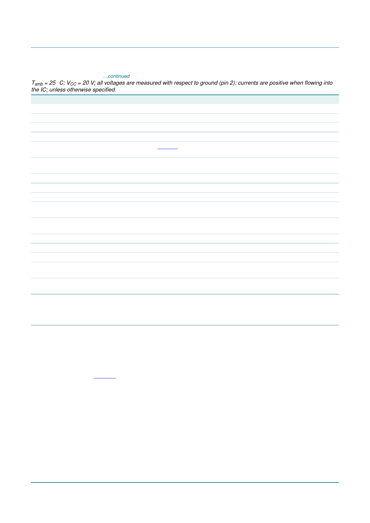
Table 5. Characteristics …continued
Tamb = 25 °C; VCC = 20 V; all voltages are measured with respect to ground (pin 2); currents are positive when flowing into
the IC; unless otherwise specified.
Symbol
Parameter
Conditions
Min Typ Max Unit
Opto output (pin OPTO)
IO(max)
maximum output current VOPTO > 5 V
VO(min)
minimum output voltage IOPTO = 4 mA
Voltage sense (pin VSENSE)
4
5
12 mA
-
-
3.5 V
Vreg(VSENSE)
regulation voltage on pin See Figure 4
VSENSE
2.475 2.5 2.525 V
II(VSENSE)
input current on pin
VSENSE
VVSENSE = Vreg(VSENSE)
−100 0
+100 nA
gm
transconductance
GB
gain bandwidth product
Current sense (pin ISENSE)
VVSENSE to IOPTO
RL = 1 kΩ
-
40 -
1
A/V
MHz
Vreg(ISENSE)
regulation voltage on pin
ISENSE
46 50 54 mV
II(reg)(ISENSE)
regulation input current VISENSE = Vreg(ISENSE)
on pin ISENSE
−200 −100 0
nA
gm
transconductance
GB
gain bandwidth product
Temperature protection
VISENSE to IOPTO
RL = 1 kΩ
-
15 -
1
-
-
A/V
MHz
Tpl(max)
maximum protection
level temperature
140 150 -
°C
Tpl(hys)
protection level
hysteresis temperature
-
12 -
°C
[1] The VCC stop voltage is Vstartup − Vhys.
11. Application information
A switched mode power supply with the TEA1761T consists of a primary side
discontinuous conduction mode flyback controller, a transformer, and an output stage with
a feedback circuit. In the output stage a MOSFET (Qsec) is used for low conduction
losses. The MOSFET is controlled by the TEA1761T. The output voltage and/or current is
also controlled by the TEA1761T via the opto coupler connection to the primary side. See
Figure 5.
The output voltage is set by resistors Rfb1 and Rfb2. The output current is controlled by
the resistor Risense. The timing for the synchronous rectifier switch is derived from the
voltage sensed on the SRSENSE pin. The resistor in the SRSENSE connection is needed
to protect the TEA1761T from excessive voltages. The SRSENSE resistor should typically
be 1 kΩ. Higher values might impair correct timing, lower values may not provide sufficient
protection.
TEA1761T_2
Product data sheet
Rev. 02 — 25 April 2007
© NXP B.V. 2007. All rights reserved.
8 of 13
Share Link: 