KCEG142 データシートの表示(PDF) - Unspecified
部品番号
コンポーネント説明
メーカー
KCEG142 Datasheet PDF : 22 Pages
| |||
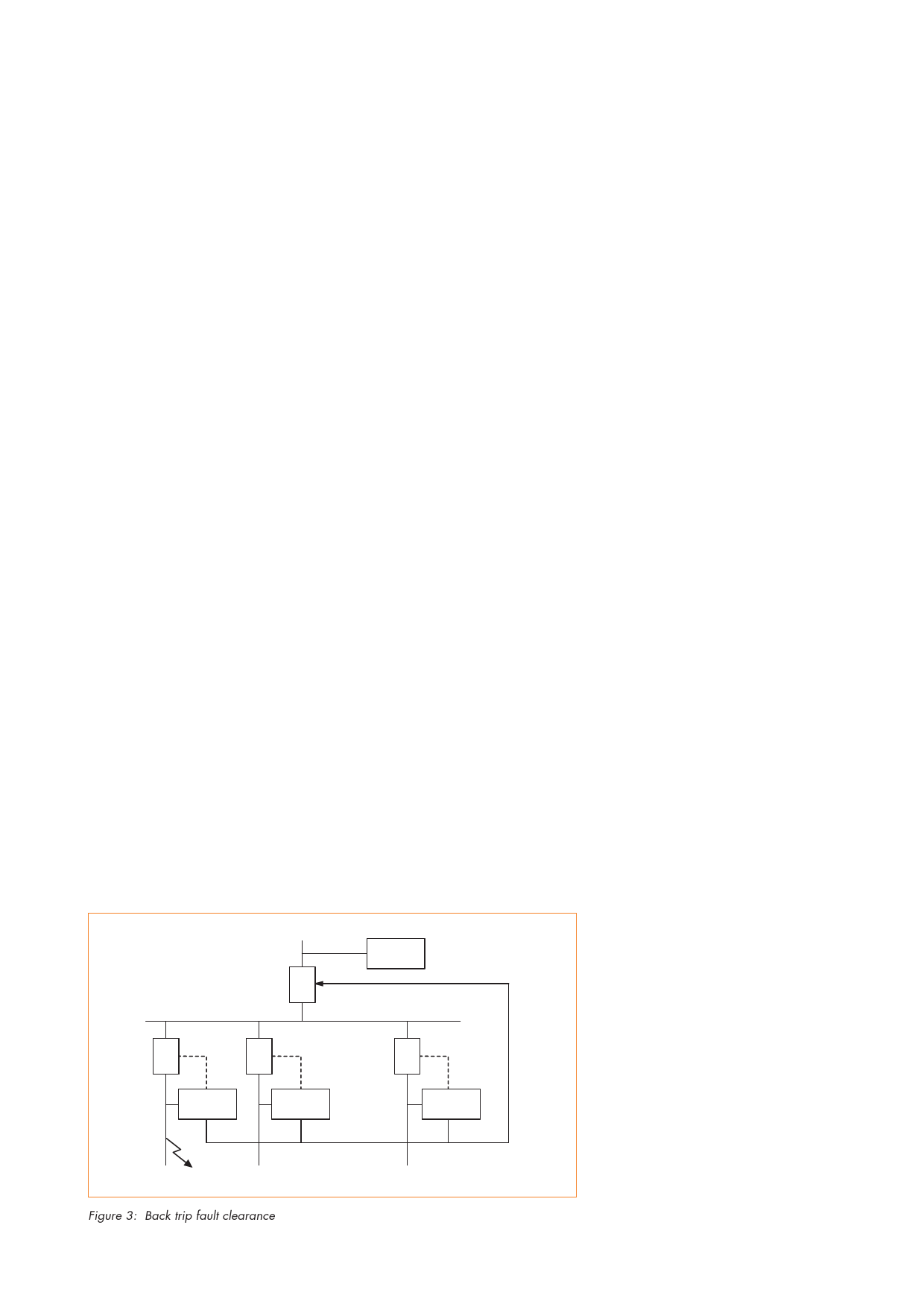
Circuit breaker failure and back-trip
This protection feature allows the relay
to trip the upstream circuit breaker
when a local breaker failure condition
is detected and can be energised both
from operation of the relay or an
external trip. Figure 3 shows a typical
back-trip method for a fault on Feeder
1 that should be cleared by Relay 2
and circuit breaker B (CB-B). If CB-B
fails to clear the fault, it will be
cleared by the back-trip contact of
Relay 2 tripping CB-A.
faults, an economical form of busbar
protection can be applied to a system.
This can be used where dedicated
busbar protection can not be justified.
Rectifier protection
A special inverse time curve provides
protection for silicon rectifiers. Where
used with the thermal overload,
instantaneous short circuit and
restricted earth fault protection, both
the transformer and rectifier can be
fully protected.
Undervoltage protection (KCEG)
A separate characteristic can be set to
provide an output for undervoltages
which are phase-phase, phase-neutral,
three phase or single phase.
An independently set timer, tV< is
used with this function which can
allow a voltage controlled overcurrent
feature to be created by switching
between different current settings in
the two groups. The undervoltage
element can be blocked when the
circuit breaker is open.
Underfrequency
A delayed underfrequency element is
available which can be used to
initiate direct load shed tripping.
Broken conductor detection
The relay can provide a broken
conductor alarm when it detects load
current in only two out of three
conductors.
Circuit breaker maintenance data
An alarm is provided to indicate the
need for circuit breaker maintenance
based upon the number of circuit
breaker operations or upon the
summated contact breaking duty.
The circuit breaker trip time is stored
in the fault records.
Busbar protection
Protection of busbars can also be
achieved by using the start and
blocking contacts of the K relays.
If in Figure 3, relay 1 has a standard
IDMT characteristic for I>, but a fast
acting I>> element (time delay of
typically 50ms) which is blocked by
the downstream relays for feeder
Incomer
CB-A
Relay 1
Back trip
CB-B
Relay 2
CB-C
Relay 3
CB-D
Relay 4
Feeder 1
Feeder 2
Figure 3: Back trip fault clearance
Feeder 3
Configuration
Logic
The configuration of the relay, to meet
the required applications, is
accomplished in software. Setting
logic function links, together with the
assignment of inputs and outputs,
define the way that the relay will
operate. This allows:
q Selection of features
q Implementation of user defined
logic using auxiliary timers
q Control of the integral disturbance
and event recorder
These may be defined by the user via
the relay front panel function keys, or
remotely by a PC via the
communications system.
Alternative setting group
Two setting groups allow the user to
assign settings for different operating
conditions. Several methods of
selecting the alternative setting group
are provided.
Ancillary Functions
Measurements
The measurement values provided by
the relay can be accessed by an
integral back-lit liquid crystal display
or via the serial port eliminating the
need for additional instrumentation to
be mounted on the panel. The
measurements can be displayed in
either primary or secondary values as
selected by the user.
The following quantities are provided
as standard:
q phase current
q neutral current
q frequency
q thermal ammeter
q peak demand ammeter
Additional values are provided by the
KCEG, as follows:
q phase voltage
q line voltage
q zero sequence voltage
q watts (single phase and three
phase)
q VArs (single phase and three
phase)
q volt amps
q power factor
4
Share Link: 