UPB1509GV データシートの表示(PDF) - NEC => Renesas Technology
部品番号
コンポーネント説明
メーカー
UPB1509GV Datasheet PDF : 16 Pages
| |||
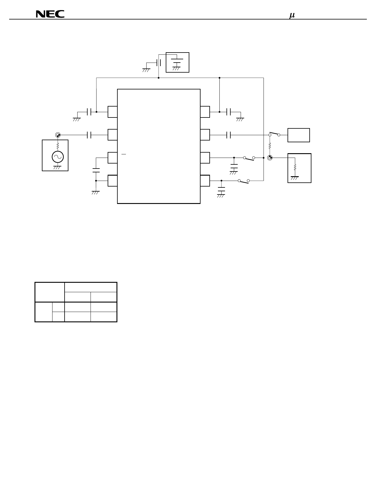
TEST CIRCUIT
1000 pF
Power Supply
PPB1509GV
C1
C2
50 Ω
C3
Signal Generator
1 VCC1
2 IN
3 IN
4 GND
C7
VCC2 8
OUT 7
SW2 6
SW1 5
C6
C5
C4
High impedance
Oscilloscope
R1
150 Ω
50 Ω
Counter
(or Spectrum Analizer)
EQUIPMENTS
Signal Generator (HP-8665A)
Counter (HP-5350B) for measuring input sensitivity (Spectrum Analyzer for measuring output frequency)
Oscilloscope for measuring output swing (In measuring output power on Spectrum Analyzer, oscilloscope should
be turned off.)
Divide Ratio Setting
SW2
H
L
H
1/2
1/4
SW1
L
1/4
1/8
H: SW pin should be connected to VCC1 pin.
L: SW pin should be opened or connected to GND.
6
Share Link: 