CAT25C03U14ATE13 データシートの表示(PDF) - Catalyst Semiconductor => Onsemi
部品番号
コンポーネント説明
メーカー
CAT25C03U14ATE13 Datasheet PDF : 12 Pages
| |||
CAT25C11/03/05/09/17
SPI modes (0,0 & 1,1).
SCK: Serial Clock
SCK is the serial clock pin. This pin is used to synchronize
the communication between the microcontroller and the
25C11/03/05/09/17. Opcodes, byte addresses, or data
present on the SI pin are latched on the rising edge of the
SCK. Data on the SO pin is updated on the falling edge of
the SCK for SPI modes (0,0 & 1,1).
CS: Chip Select
CS is the Chip select pin. CS low enables the CAT25C11/
03/05/09/17 and CS high disables the CAT25C11/03/05/
09/17. CS high takes the SO output pin to high impedance
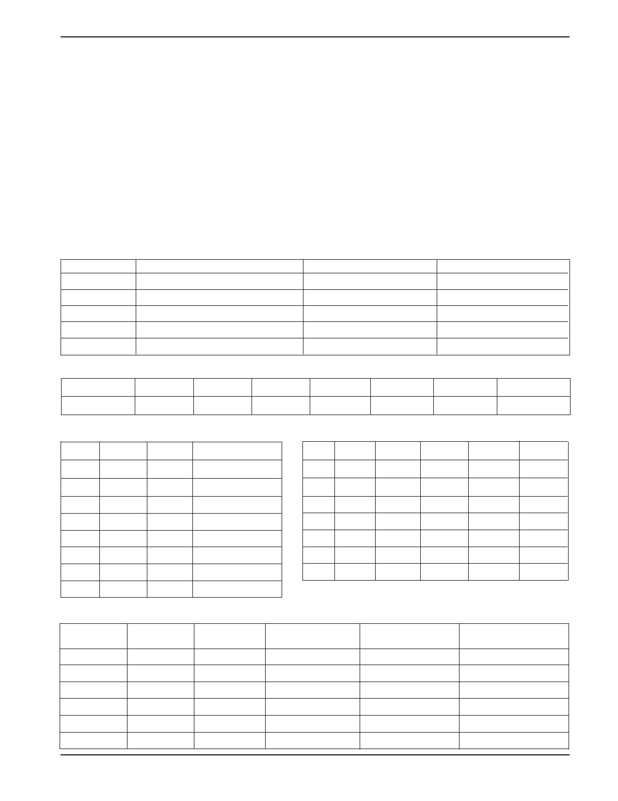
BYTE ADDRESS
and forces the devices into a Standby Mode (unless an
internal write operation is underway) The CAT25C11/03/
05/09/17 draws ZERO current in the Standby mode. A
high to low transition on CS is required prior to any
sequence being initiated. A low to high transition on CS
after a valid write sequence is what initiates an internal
write cycle.
WP: Write Protect
WP is the Write Protect pin. The Write Protect pin will allow
normal read/write operations when held high. When WP is
tied low and the WPEN bit in the status register is set to "1",
all write operations to the status register are inhibited. WP
going low while CS is still low will interrupt a write to the
status register. If the internal write cycle as already been
initiated, WP going low will have no effect on any write
Device
Address Significant Bits
Address Don't Care Bits # Address Clock Pulse
CAT25C11
A6 - A0
A7
8
CAT25C03
A7 - A0
—
8
CAT25C05 A7 - A0 (A8 = X bit from Opcode)
—
8
CAT25C09
A9 - A0
A15 - A10
16
CAT25C17
A10 - A0
A15 - A11
16
STATUS REGISTER
7
6
WPEN
1
5
4
3
2
1
0
1
BP2
BP1
BP0
WEL
RDY
MEMORY PROTECTION
BP2 BP1 BP0
0
0
0
Non-Protection
0
0
1
Q1 Protected
0
1
0
Q2 Protected
0
1
1
Q3 Protected
1
0
0
Q4 Protected
1
0
1
H1 Protected
1
1
0
P0 Protected
1
1
1
Pn Protected
WRITE PROTECT ENABLE OPERATION
25C11 25C03 25C05 25C09 25C17
Q1 00-1F 00-3F 000-07F 000-0FF 000-1FF
Q2 20-3F 40-7F 080-0FF 100-1FF 200-3FF
Q3 40-5F 80-BF 100-17F 200-2FF 400-5FF
Q4 60-7F C0-FF 180-1FF 300-3FF 600-7FF
H1 00-3F 00-7F 000-0FF 000-1FF 000-3FF
P0 00-0F 00-0F 000-00F 000-01F 000-01F
Pn 70-7F F0-FF 1F0-1FF 3E0-3FF 7E0-7FF
WPEN
0
0
1
1
X
X
WP
X
X
Low
Low
High
High
WEL
0
1
0
1
0
1
Protected
Blocks
Protected
Protected
Protected
Protected
Protected
Protected
Unprotected
Blocks
Protected
Writable
Protected
Writable
Protected
Writable
Status
Register
Protected
Writable
Protected
Protected
Protected
Writable
5
Doc. No. 1017, Rev. J
Share Link: 