135D355X0075C2 гғҮгғјгӮҝгӮ·гғјгғҲгҒ®иЎЁзӨәпјҲPDFпјү - Vishay Semiconductors
йғЁе“Ғз•ӘеҸ·
гӮігғігғқгғјгғҚгғігғҲиӘ¬жҳҺ
гғЎгғјгӮ«гғј
135D355X0075C2
Vishay Semiconductors

135D355X0075C2 Datasheet PDF : 14 Pages
| |||
www.vishay.com
135D
Vishay
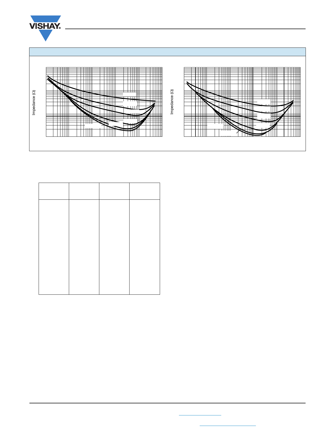
TYPICAL CURVES OF IMPEDANCE AS A FUNCTION OF FREQUENCY AT VARIOUS TEMPERATURES
вҖңCвҖқ Case 33 ОјF, 50 V Capacitors
100
вҖңKвҖқ Case 56 ОјF, 125 V Capacitors
100
10
10
- 55 В°C
- 40 В°C
- 55 В°C
1.0
- 20 В°C
1.0
- 40 В°C
- 20 В°C
+ 125 В°C
+ 25 В°C
+ 85 В°C
+ 125 В°C
+ 25 В°C
0.1
100
1K
10K
100K
Frequency (Hz)
0.1
1M
10M
100
+ 85 В°C
1K
10K
100K
Frequency (Hz)
1M
10M
PERFORMANCE CHARACTERISTICS
1. Operating Temperature: Capacitors are designed to
operate over a temperature range of - 55 В°C to + 200 В°C.
UP TO
+ 85 В°C
(V)
AT
+ 125 В°C
(V)
AT
+ 175 В°C
(V)
AT
+ 200 В°C
(V)
6
4
3
8
5
4
10
7
5
15
10
8
25
15
13
30
20
15
(1)
35
23
18
50
30
25
60
40
30
75
50
38
100
65
50
125
85
63
Note
(1)Consult Vishay Sprague for information at + 200 В°C. See
paragraph 9.3.
2. DC Working Voltage: The DC working voltage is the
maximum operating voltage for continuous duty at the
rated temperature.
3. Surge Voltage: The surge voltage rating is the
maximum voltage to which the capacitors should be
subjected under any conditions. This includes
transients and peak ripple at the highest line voltage.
3.1 The surge voltage of capacitors is 115 % of rated DC
working voltage.
3.2 Surge Voltage Test: Capacitors shall withstand the
surge voltage applied through a 1000 пҒ— Вұ 10 % resistor
in series with the capacitor and voltage source at the
rate of one-half minute on, four and one-half minutes
off, for 1000 successive test cycles at + 85 В°C or
+ 125 В°C.
3.3 Following the surge voltage test, the capacitance at
+ 25 В°C shall not have changed by more than Вұ 10 %
and the equivalent series resistance and DC leakage
current will not exceed the values shown in the
Standard Ratings table for each capacitor.
4. Capacitance Tolerance: The capacitance of all
capacitors shall be within the specified tolerance limits
of the nominal rating.
4.1 Measurements shall be made by the bridge method at
or referred to a frequency of 120 Hz at a temperature of
+ 25 В°C. The maximum voltage applied to the capacitors
during measurement shall be 1 VRMS. Measurement
accuracy of the bridge shall be within Вұ 2 %.
5. Capacitance Change With Temperature: The
capacitance change with temperature shall not exceed
the values given in the Standard Ratings table for each
capacitor.
6. Equivalent Series Resistance: Measurements shall be
made by the bridge method at, or referred to, a
frequency of 120 Hz at a temperature of + 25 В°C. A
maximum of 1 VRMS shall be applied during
measurement.
6.1 The equivalent series resistance shall not exceed the
maximum value in ohms listed in the Standard Ratings
table for each capacitor.
Revision: 09-Apr-13
7
Document Number: 40024
For technical questions, contact: tantalum@vishay.com
THIS DOCUMENT IS SUBJECT TO CHANGE WITHOUT NOTICE. THE PRODUCTS DESCRIBED HEREIN AND THIS DOCUMENT
ARE SUBJECT TO SPECIFIC DISCLAIMERS, SET FORTH AT www.vishay.com/doc?91000
Share Link: