135D357X0025K2 гғҮгғјгӮҝгӮ·гғјгғҲгҒ®иЎЁзӨәпјҲPDFпјү - Vishay Semiconductors
йғЁе“Ғз•ӘеҸ·
гӮігғігғқгғјгғҚгғігғҲиӘ¬жҳҺ
гғЎгғјгӮ«гғј
135D357X0025K2
Vishay Semiconductors

135D357X0025K2 Datasheet PDF : 14 Pages
| |||
www.vishay.com
6.2 The dissipation factor may be calculated from the
equivalent series resistance and capacitance values as
shown:
DF
=
2----пҒ°----f--R----C---
104
where:
DF = Dissipation Factor in %
R = ESR in пҒ—
C = Capacitance in ОјF
f = Frequency in Hz
At 120 Hz, the above equation becomes:
DF
=
-R-----x-----C---
13.26
пҖ
For example, percent dissipation factor of a 30 ОјF, 6 V
capacitor, which has a maximum ESR of 4.0 пҒ— at
+ 25 В°C and 120 Hz, would be calculated as shown:пҖ
DF
=
2----пҒ°-----x-----1---2----0-----x----4------x----3----0-
104
=
4------x----3----0-
13.26
=
9.05 %
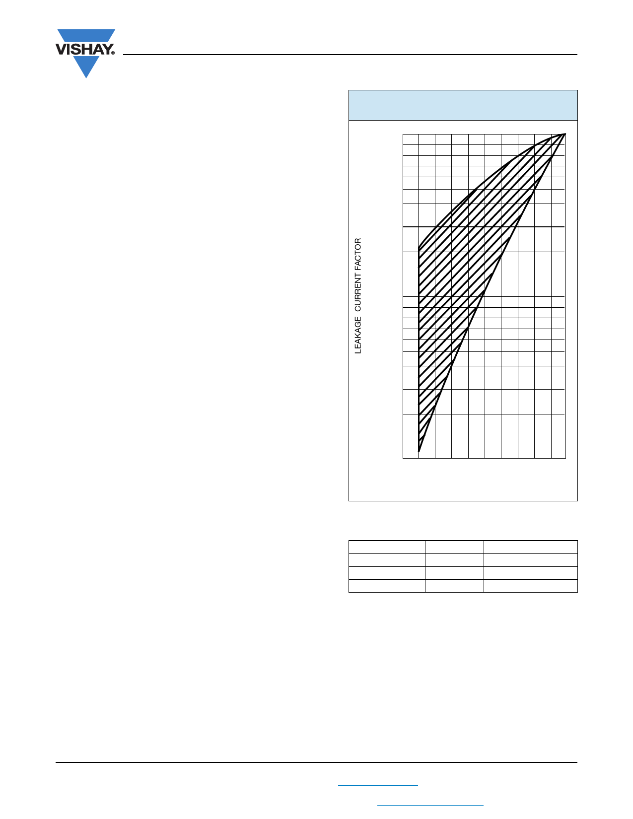
7. Leakage Current: Measurements shall be made at the
applicable rated working voltage at + 25 В°C Вұ 5 В°C
through application of a steady source of power, such
as a regulated power supply. A 1000 пҒ— resistor to limit
the charging current shall be conected in series with
each capacitor under test. Rated working voltage shall
be applied to capacitors for 5 minutes before making
leakage current measurements.
7.1 The maximum leakage current for any capacitor shall
not exceed the maximum value in mA listed in the
Standard Ratings and Extended Ratings table for each
capacitor.
Note
вҖў Leakage current varies with applied voltage. See graph next
column for the appropriate adjustment factor
8. Low Temperature Impedance: The impedance of any
capacitor at - 55 В°C at 120 Hz, shall not exceed the
values given in the Standard Ratings and Extended
Ratings tables.
9. Life Test: Capacitors are capable of withstanding a
2000 h life test at a temperature of + 85 В°C or + 125 В°C
at the applicable rated DC working voltage.
9.1 Following the life test, the capacitors shall be returned
to 25 В°C Вұ 5 В°C. The leakage current, measured at the
+ 85 В°C rated voltage, shall not be in excess of the
original requirement; the capacitance value shall not
exceed 150 % of the initial requirement; the
capacitance value shall not change more than 10 %
from the initial measurement.
135D
Vishay
TYPICAL LEAKAGE CURRENT FACTOR
RANGE
1.0
0.9
0.8
0.7
0.6
0.5
0.4
0.3
0.2
0.1
0.09
0.08
0.07
0.06
0.05
0.04
0.03
0.02
0.01
0
10 20 30 40 50 60 70 80 90 100
PERCENT OF RATED VOLTAGE
9.3 Capacitors are capable of withstanding life test at the
following conditions:
TEMPERATURE
+ 175 В°C
+ 175 В°C
+ 200 В°C
HOURS
2000
300
300
% RATED VOLTAGE
50
65
60
9.4 Following the life test, the capacitors shall be returned
to + 25 В°C Вұ 5 В°C. The leakage current, at the rated
voltage shall not exceed 200 % of the original
requirement or Вұ 10 ОјA, whichever is greater; the
equivalent series resistance shall not be greater than
200 % of the original requirement; the capacitance
value shall not increase by more than 10 % or decrease
by more than 20 % from the initial measurement.пҖ
Revision: 09-Apr-13
8
Document Number: 40024
For technical questions, contact: tantalum@vishay.com
THIS DOCUMENT IS SUBJECT TO CHANGE WITHOUT NOTICE. THE PRODUCTS DESCRIBED HEREIN AND THIS DOCUMENT
ARE SUBJECT TO SPECIFIC DISCLAIMERS, SET FORTH AT www.vishay.com/doc?91000
Share Link: