MPT-8 データシートの表示(PDF) - Microsemi Corporation
部品番号
コンポーネント説明
メーカー
MPT-8 Datasheet PDF : 3 Pages
| |||
SCOTTSDALE DIVISION
1N6356 thru 1N6372
or MPT-5 thru MPT-45C
1500 W LOW CLAMPING FACTOR
TRANSIENT VOLTAGE SUPPRESSOR
ELECTRICAL CHARACTERISTICS @ 25oC (Unidirectional)
MICROSEMI
PART NUMBER
1N6356
MPT-5
1N6357
MPT-8
1N6358
MPT-10
1N6359
MPT-12
1N6360
MPT-15
1N6361
MPT-18
1N6362
MPT-22
1N6363
MPT-36
1N6364
MPT-45
STAND-OFF
VOLTAGE
(NOTE 1)
VWM
VOLTS
5.0
8.0
10.0
12.0
15.0
18.0
22.0
36.0
45.0
MAXIMUM
REVERSE
LEAKAGE
@VWM
ID
µA
300
25
2
2
2
2
2
2
2
MINIMUM*
BREAKDOWN
VOLTAGE
@ 1.0 mA
V(BR) (min)
VOLTS
6.0
9.4
11.7
14.1
17.6
21.2
25.9
42.4
52.9
MAXIMUM
CLAMPING
VOLTAGE
(Fig. 2)
IPP1 = 1A
VC
VOLTS
7.1
11.3
13.7
16.1
20.1
24.2
29.8
50.6
63.3
VF at 100 amps peak is 3.5 volts maximum at 8.3 ms half-sine wave.
MAXIMUM
CLAMPING
VOLTAGE
(Fig. 2)
@ IPP2 = 10A
VC
VOLTS
7.5
11.5
14.1
16.5
20.6
25.2
32.0
54.3
70.0
MAXIMUM
PEAK PULSE
CURRENT
IPP3
A
160
100
90
70
60
50
40
23
19
ELECTRICAL CHARACTERISTICS @ 25oC (Bidirectional)
MPT-5C
5.0
300
6.0
7.1
7.5
160
1N6365
MPT-8C
8.0
25
9.4
11.4
11.6
100
1N6366
MPT-10C
10.0
2
11.7
14.1
14.5
90
1N6367
MPT-12C
12.0
2
14.1
16.7
17.1
70
1N6368
MPT-15C
15.0
2
17.6
20.8
21.4
60
1N6369
MPT-18C
18.0
2
21.2
24.8
25.5
50
1N6370
MPT-22C
22.0
2
25.9
30.8
32.0
40
1N6371
MPT-36C
36.0
2
42.4
50.6
54.3
23
1N6372
MPT-45C
45.0
2
52.9
63.3
70.0
19
C Suffix indicates Bidirectional
NOTE 1: TVS devices are normally selected according to the reverse “Stand Off Voltage” (VWM) which should be equal to or greater than the DC or
continuous peak operating voltage level.
* The minimum breakdown voltage as shown takes into consideration the + volt tolerance normally specified for power supply regulation on
most integrated circuit manufacturers data sheets. Similar devices are available with reduced clamping voltages where tighter regulated
power supply voltages are employed.
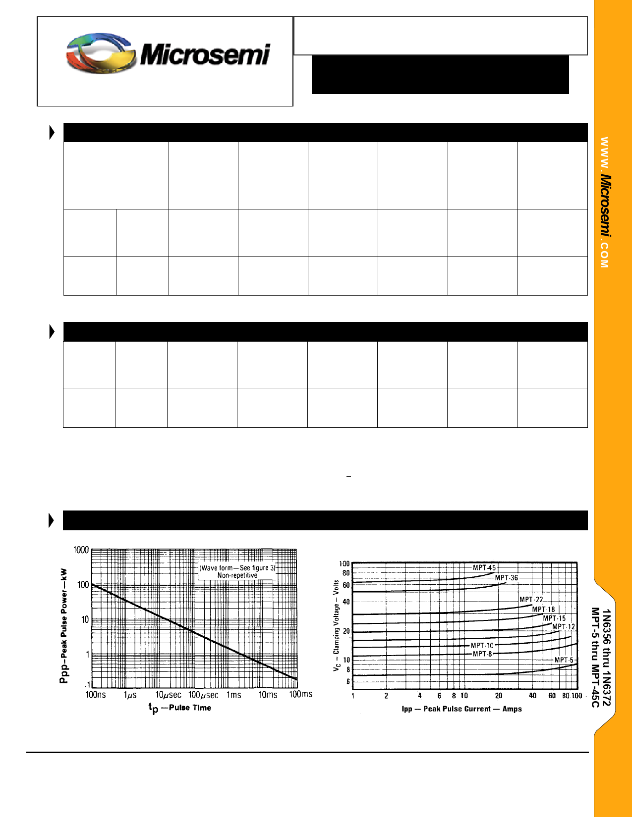
GRAPHS
FIGURE 1
Peak Pulse Power vs. Pulse Time
FIGURE 2
Typical Characteristic Clamping Voltage
vs. Peak Pulse Current
Copyright 2002
11-06-2003 REV A
Microsemi
Scottsdale Division
8700 E. Thomas Rd. PO Box 1390, Scottsdale, AZ 85252 USA, (480) 941-6300, Fax: (480) 947-1503
Page 2
Share Link: 