A3361EEUA-TL データシートの表示(PDF) - Allegro MicroSystems
部品番号
コンポーネント説明
メーカー
A3361EEUA-TL Datasheet PDF : 12 Pages
| |||
3361 AND 3362
2-WIRE,
CHOPPER-STABILIZED,
HALL-EFFECT SWITCHES
FUNCTIONAL DESCRIPTION
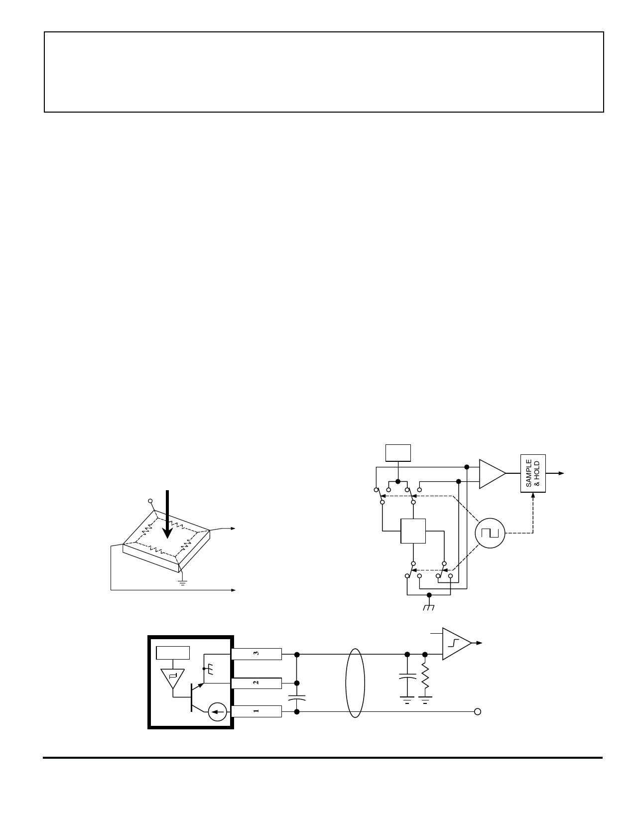
Chopper-Stabilized Technique. The Hall element can be
considered as a resistor array similar to a Wheatstone bridge. A
large portion of the offset is a result of the mismatching of these
resistors. These devices use a proprietary dynamic offset
cancellation technique, with an internal high-frequency clock to
reduce the residual offset voltage of the Hall element that is
normally caused by device overmolding, temperature dependen-
cies, and thermal stress. The chopper-stabilizing technique
cancels the mismatching of the resistor circuit by changing the
direction of the current flowing through the Hall plate using
CMOS switches and Hall voltage measurement taps, while
maintaing the Hall-voltage signal that is induced by the external
magnetic flux. The signal is then captured by a sample-and-
hold circuit and further processed using low-offset bipolar
circuitry. This technique produces devices that have an
extremely stable quiescent Hall output voltage, are immune to
thermal stress, and have precise recoverability after temperature
cycling. This technique will also slightly degrade the device
output repeatability. A relatively high sampling frequency is
used in order that faster signals can be processed.
More detailed descriptions of the circuit operation can be
found in: Technical Paper STP 97-10, Monolithic Magnetic
Hall Sensor Using Dynamic Quadrature Offset Cancellation
and Technical Paper STP 99-1, Chopper-Stabilized Amplifiers
With A Track-and-Hold Signal Demodulator.
Operation. As shown in the output characteristic graphs, the
output of the A3362 turns on when a magnetic field (south pole)
perpendicular to the Hall sensor is increased above the operate
point threshold (BOP). After turn on, the output will source
current equal to the device operating current plus a current
source (IGND(H)). When the magnetic field is decreased below
the release point (BRP), the output turns off and will source
current equal only to the Hall-effect sensor operating current
(IGND(L)). The A3361 output is inverted and the device turns off
at BOP and on at BRP. The difference in the magnetic operate
and release points is the hysteresis (Bhys) of the device. The
hysteresis allows clean switching of the output even in the
presence of external mechanical vibration or electrical noise.
Applications. It is strongly recommended that an external
bypass capacitor be connected (in close proximity to the Hall
sensor) between the supply and ground of the device to reduce
both external noise and noise generated by the chopper-
stabilization technique.
Extensive applications information on magnets and Hall-
effect sensors is also available in the Allegro Electronic Data
Book AMS-702 or Application Note 27701 or
www.allegromicro.com
REG
B
+V
—
HALL
VOLTAGE
+
Dwg. AH-011-2
'UA' PACKAGE
X
0.1 µF
X
0.95 V
–
+
100 Ω
SUPPLY
Dwg. EH-011-2A
Dwg. EH-012
www.allegromicro.com
7
Share Link: 