232259 データシートの表示(PDF) - Vishay Semiconductors
部品番号
コンポーネント説明
メーカー
232259 Datasheet PDF : 18 Pages
| |||
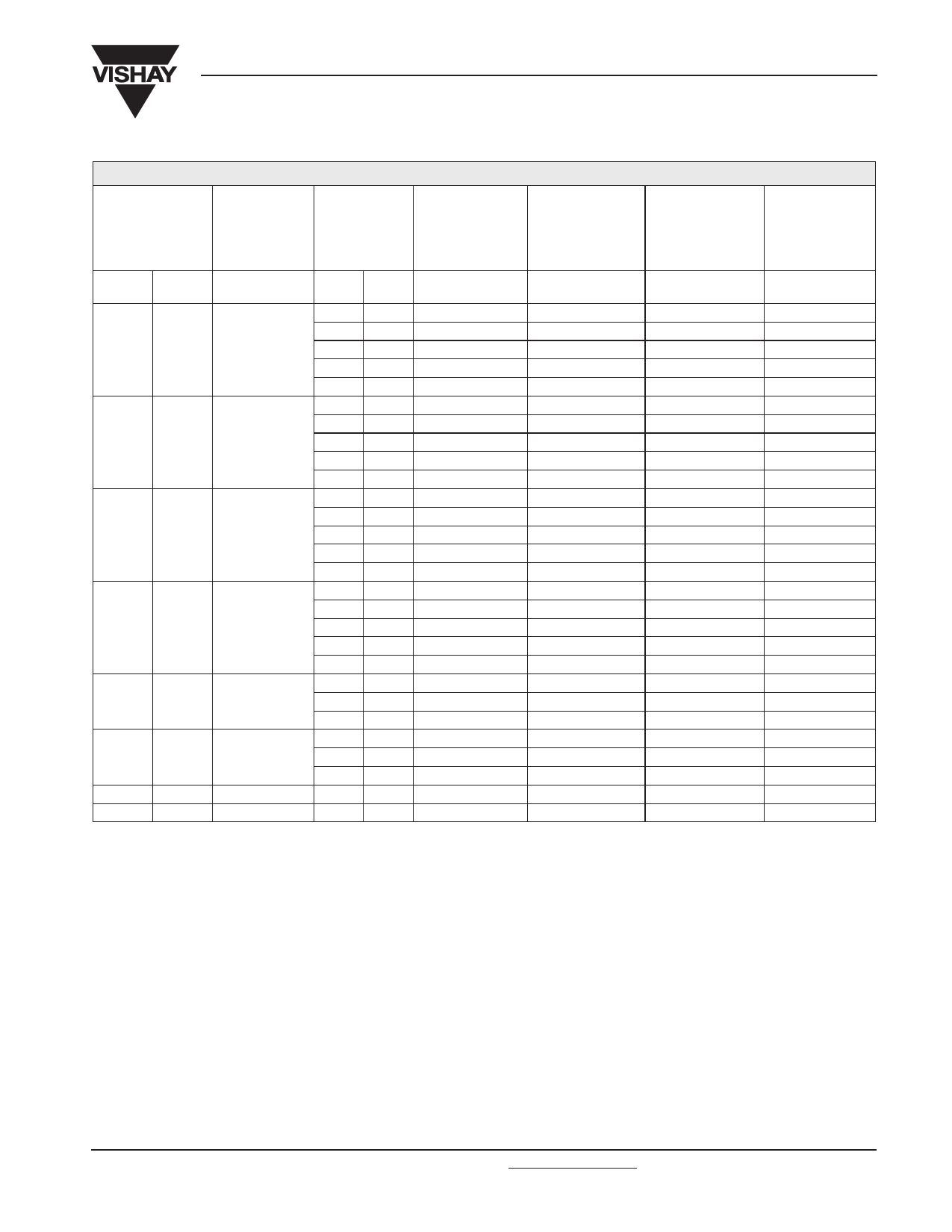
Varistors
2322 59. .....
Vishay BCcomponents
ELECTRICAL DATA AND ORDERING INFORMATION
MAXIMUM
CONTINUOUS
VOLTAGE
RMS(2)
DC
(V)
(V)
VOLTAGE(3)at
1 mA
(V)
MAXIMUM
VOLTAGE at
STATED
CURRENT
V
I
(V)
(A)
MAXIMUM
ENERGY(4)
(10 × 1000 µs)
(J)
MAXIMUM
NON-REP.
TRANSIENT
CURRENT(5)
Inrp (8 × 20 µs)
(A)
350
460
385
505
420
560
460
615
510
670
550
745
625
825
680
895
560
620
680
750
820
910
1000
1100
940
920
920
920
920
1 000
1 025
1 025
1 025
1 025
1 100
1 120
1 120
1 120
1 120
1 200
1 240
1 240
1 240
1 240
1 355
1 355
1 355
1 500
1 500
1 500
1 650
1 815
5.0
10.0
25.0
50.0
100.0
5.0
10.0
25.0
50.0
100.0
5.0
10.0
25.0
50.0
100.0
5.0
10.0
25.0
50.0
100.0
25.0
50.0
100.0
25.0
50.0
100.0
100.0
100.0
19.5
39.0
78.0
156.0
312.0
18.0
51.0
67.0
110.0
328.0
20.0
56.0
73.0
120.0
344.0
21.0
63.0
82.0
135.0
360.0
89.0
145.0
376.0
98.0
160.0
408.0
448.0
496.0
400
1 200
2 500
4 500
6 500
400
1 200
2 500
4 500
6 500
400
1 200
2 500
4 500
6 500
400
1 200
2 500
4 500
6 500
2 500
4 500
6 500
2 500
4 500
6 500
6 500
6 500
TYPICAL
CAPACITANCE at
1 kHZ
(pF)
42
110
200
325
660
40
95
180
280
570
35
85
165
250
510
30
75
150
225
460
135
220
450
120
180
370
320
270
CATALOG
NUMBERS(1)
2322 ... .....
592 .3516(6)
593 .3516(6)
594 .3516(6)
595 .3516(6)
596 .3516
592 .3816(6)
593 .3816(6)
594 .3816(6)
595 .3816(6)
596 .3816
592 .4216(6)
593 .4216(6)
594 .4216(6)
595 .4216(6)
596 .4216
592 .4616(6)
593 .4616(6)
594 .4616(6)
595 .4616(6)
596 .4616
594 .5116(6)
595 .5116(6)
596 .5116
594 .5516(6)
595 .5516(6)
596 .5516
596 .6216
596 .6816
Notes
1. Lists with products certified according to UL (E98144), VDE (122380E + 40002622), CSA (219883) and CECC (42201-001) are available at
www.vishay.com or on request.
2. The sinusoidal voltage is assumed as the normal operating condition. If a non-sinusoidal voltage is present, type selection should be based
on multiplying the peak voltage by a factor of 0.707.
3. The voltage measured at 1 mA meets the requirements of “paragraph 4.3 of CECC specification 42000”.
The tolerance on the voltage at 1 mA is ±10%.
4. High energy surges are generally of longer duration. The maximum energy for one pulse of 10 × 1000 µs is given as a reference for longer
duration pulses. This pulse can be characterised by peak current (Ip) and pulse width t2 (virtual time of half Ip value, following “IEC 60060-2,
section 6” ). If Vp is the clamping voltage corresponding to Ip, the energy absorbed in the varistor is determined by the formula:
E = K × Vp × Ip × t2
where:
a) K is dependent on the value of t2 when the value of t1 is between 8 µs and 10 µs; see Peak Current as a Function of Pulse Width drawing.
5. A current wave of 8 × 20 µs (requirement of “paragraph B.2.10.1 of CECC specification 42000” ) is used as a standard for pulse current and
clamping voltage ratings. The maximum non-repetitive transient current is given for one pulse applied during the life of the component.
6. Replace the last digit of the catalog number with a ‘7’ for ordering on tape in ammopack.
Document Number: 29081
Revision: 28-Apr-04
For technical questions contact: nlr.europe@vishay.com
www.vishay.com
29
Share Link: 