24C02SC データシートの表示(PDF) - Microchip Technology
部品番号
コンポーネント説明
メーカー
24C02SC Datasheet PDF : 12 Pages
| |||
24C01SC/02SC
8.0 PAD DESCRIPTIONS
8.1 SDA Serial Address/Data Input/Output
This is a bi-directional pad used to transfer addresses
and data into and data out of the device. It is an open
drain terminal, therefore the SDA bus requires a pull-up
resistor to VCC (typical 10KΩ for 100 kHz, 1KΩ for 400
kHz).
For normal data transfer SDA is allowed to change only
during SCL low. Changes during SCL high are reserved
for indicating the START and STOP conditions.
8.2 SCL Serial Clock
This input is used to synchronize the data transfer from
and to the device.
8.3 DC Don’t Connect
This pad is used for test purposes and should not be
bonded out. It will be pulled to VSS through an internal
resistor.
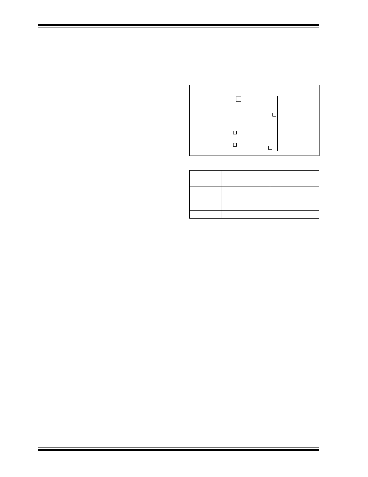
9.0 DIE CHARACTERISTICS
Figure 9-1 shows the die layout of the 24C01SC/02SC,
including bondpad positions. Table 9-1 shows the
actual coordinates of the bondpad midpoints with
respect to the center of the die.
FIGURE 9-1: DIE LAYOUT
DIP
VSS
VCC
SDA
DC
SCL
TABLE 9-1: BONDPAD COORDINATES
Pad Name
Pad Midpoint,
X dir.
Pad Midpoint,
Y dir.
VSS
SDA
-495.000
-605.875
749.130
-271.875
SCL
479.875
-746.625
VCC
605.875
-261.375
Note 1: Dimensions are in microns.
2: Center of die is at the 0,0 point.
DS21170A-page 8
Preliminary
© 1996 Microchip Technology Inc.
Share Link: 