29C516E データシートの表示(PDF) - Atmel Corporation
部品番号
コンポーネント説明
メーカー
29C516E Datasheet PDF : 17 Pages
| |||
29C516E
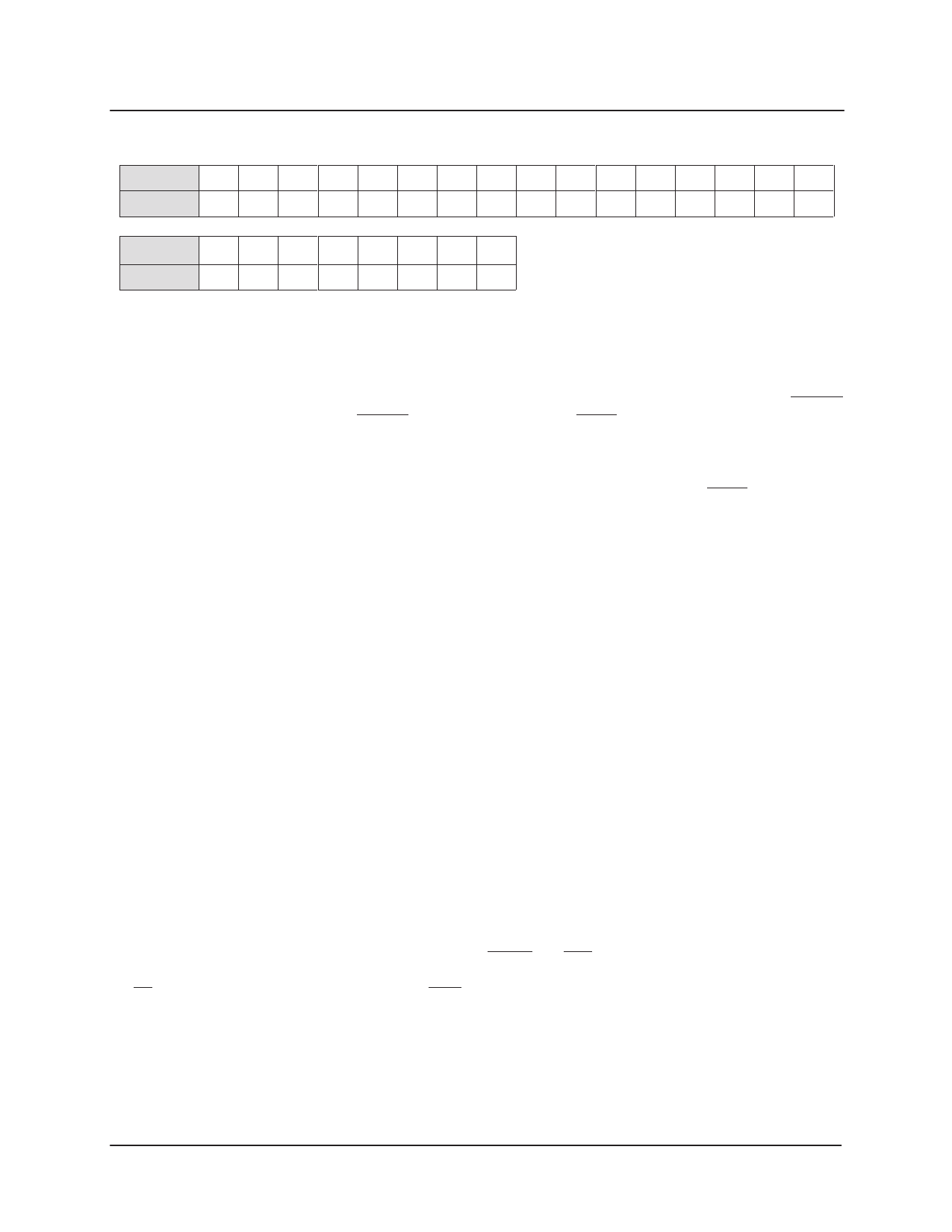
Table 7: Single Bit Error
MD[..]
SY(hexa)
[15] [14] [13] [12] [11] [10] [9] [8] [7] [6] [5] [4] [3] [2] [1] [0]
34h 2Ah 29h 25h 32h 1Ah 16h 13h 31h 23h 15h 0Bh 2Ch 1Ch 0Eh 0Dh
MC[..]
SY(hexa)
[–] [–] [5] [4] [3] [2] [1] [0]
––h ––h 20h 10h 08h 04h 02h 01h
8.3. Double–Bit Error
If two errors occur, there will be 2, 3, 4, 5, 6 or 8 bits set
to one in the syndrome byte. The syndrome value
generated by a double–bit error does not take place of a
syndrome value generated by a single–bit error. Then,
only the non correctable error flag NCERR will be
8.4. Triple–Bit Error
When three errors are detected, an error flag is set low as
warning to the system. But the generated syndrome can
have the listed value of single–bit error. The device must
be in detect mode to prevent false correction occurrence.
Example: If MD[0], MD[9] and MC[0] are corrupted, the
syndrome value is ”1Ah ”.
8.5. 4–bit Wide Memory Error
The 8 check–bit code can be used to provide error
detection for up to 4 errors occur in the following groups:
MD[15..12], MD[11..8], MD[7..4], MD[3..0], MC[7..4]
and MC[3..0]. The 29C516E EDAC can flag any number
of errors in 4–bit wide memory chip.
8.6. 8–bit Wide Memory Error
The 8 check–bit code can be used to provide error
detection for up to 8 errors occurring in the following
groups: MD[15..8], MD[7..0] and MC[7..0].
The 29C516E EDAC can flag any number of errors in
8–bit wide memory chip. A special attention must be
taken, multi–bit error ( 3) located into the defined groups
9. Transactions
activated to indicate that errors are present but cannot be
corrected.
Example: If MD[5] and MC[7] are incorrect, syndrome
bits [0], [2], [4] and [6] are set to one (SY=55h ), NCERR
is set low and CERR remains at high level.
This is decoded by the 29C516E EDAC as being a
correctable error on MD[10]. The CERR flag is set low
and correction would take place if the device is in correct
mode. This would cause more errors.
A special attention must be taken, multi–bit error ( 3)
located into the defined groups can provide the syndrome
byte of a single–bit error.
Example: If MD[11], MD[10], MD[9] and MD[8] are in
error, the syndrome code is ”AD h ”.
can provide the syndrome byte of a single–bit error.
Example: If MD[13], MD[12], MD[10] and MD[9] are in
error, the syndrome code is ”40h ”. (In 6 check–bit
coding, the syndrome code should have been ”00h ”, the
”No Error Detected” value.) Note that the syndrome code
”40 h ” is also the code for MC[6] in error.
Transactions Three types of transactions may be done:
9.1. Memory Read
The TRANS pin is driven at a high level to select the
access to the memory. The external arbiter drives the
U2/U1 pin and dispatches the commands RD/WRx,
MEMx and ENx. All transaction managed by the master
user can be listened by the second user.
9
Rev. E (03 2007)
Share Link: 