2SC5712(2001) データシートの表示(PDF) - Toshiba
部品番号
コンポーネント説明
メーカー
2SC5712 Datasheet PDF : 5 Pages
| |||
2SC5712
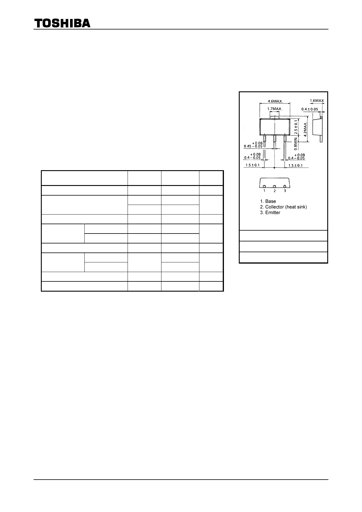
TOSHIBA Transistor Silicon NPN Epitaxial Type
2SC5712
High-Speed Switching Applications
DC-DC Converter Applications
DC-AC Converter Applications
Industrial Applications
Unit: mm
· High DC current gain: hFE = 400 to 1000 (IC = 0.3 A)
· Low collector-emitter saturation voltage: VCE (sat) = 0.14 V (max)
· High-speed switching: tf = 120 ns (typ.)
Maximum Ratings (Ta = 25°C)
Characteristics
Symbol
Rating
Unit
Collector-base voltage
Collector-emitter voltage
Emitter-base voltage
Collector current
DC
Pulse
Base current
Collector power
dissipation
DC
t = 10 s
Junction temperature
Storage temperature range
VCBO
100
V
VCEX
80
V
VCEO
50
VEBO
7
V
IC
3.0
A
ICP
5.0
IB
300
mA
PC
1.0
W
(Note)
2.5
Tj
150
°C
Tstg
-55 to 150
°C
Note: Mounted on FR4 board (glass epoxy, 1.6 mm thick, Cu area:
645 mm2)
JEDEC
―
JEITA
SC-62
TOSHIBA
2-5K1A
Weight: 0.05 g (typ.)
Electrical Characteristics (Ta = 25°C)
Characteristics
Collector cut-off current
Emitter cut-off current
Collector-emitter breakdown voltage
DC current gain
Collector-emitter saturation voltage
Base-emitter saturation voltage
Collector output capacitance
Rise time
Switching time
Storage time
Fall time
Symbol
Test Condition
ICBO
IEBO
V (BR) CEO
hFE (1)
hFE (2)
VCE (sat)
VBE (sat)
Cob
tr
tstg
tf
VCB = 100 V, IE = 0
VEB = 7 V, IC = 0
IC = 10 mA, IB = 0
VCE = 2 V, IC = 0.3 A
VCE = 2 V, IC = 1 A
IC = 1 A, IB = 20 mA
IC = 1 A, IB = 20 mA
VCB = 10 V, IE = 0, f = 1 MHz
See Figure 1 circuit diagram.
VCC ~- 30 V, RL = 30 W
IB1 = -IB2 = 33.3 mA
Min Typ. Max Unit
¾
¾
100
nA
¾
¾
100
nA
50
¾
¾
V
400
¾ 1000
200
¾
¾
¾
¾
0.14
V
¾
¾
1.10
V
¾
13
¾
pF
¾
40
¾
¾
500
¾
ns
¾
120
¾
1
2001-12-17
Share Link: 