2SC5714(2006) データシートの表示(PDF) - Toshiba
部品番号
コンポーネント説明
メーカー
2SC5714 Datasheet PDF : 5 Pages
| |||
Electrical Characteristics (Ta = 25°C)
Characteristics
Collector cut-off current
Emitter cut-off current
Collector-emitter breakdown voltage
DC current gain
Collector-emitter saturation voltage
Base-emitter saturation voltage
Collector output capacitance
Rise time
Switching time
Storage time
Fall time
Symbol
Test Condition
ICBO
IEBO
V (BR) CEO
hFE (1)
hFE (2)
VCE (sat)
VBE (sat)
Cob
tr
tstg
tf
VCB = 40 V, IE = 0
VEB = 7 V, IC = 0
IC = 10 mA, IB = 0
VCE = 2 V, IC = 0.5 A
VCE = 2 V, IC = 1.6 A
IC = 1.6 A, IB = 32 mA
IC = 1.6 A, IB = 32 mA
VCB = 10 V, IE = 0, f = 1 MHz
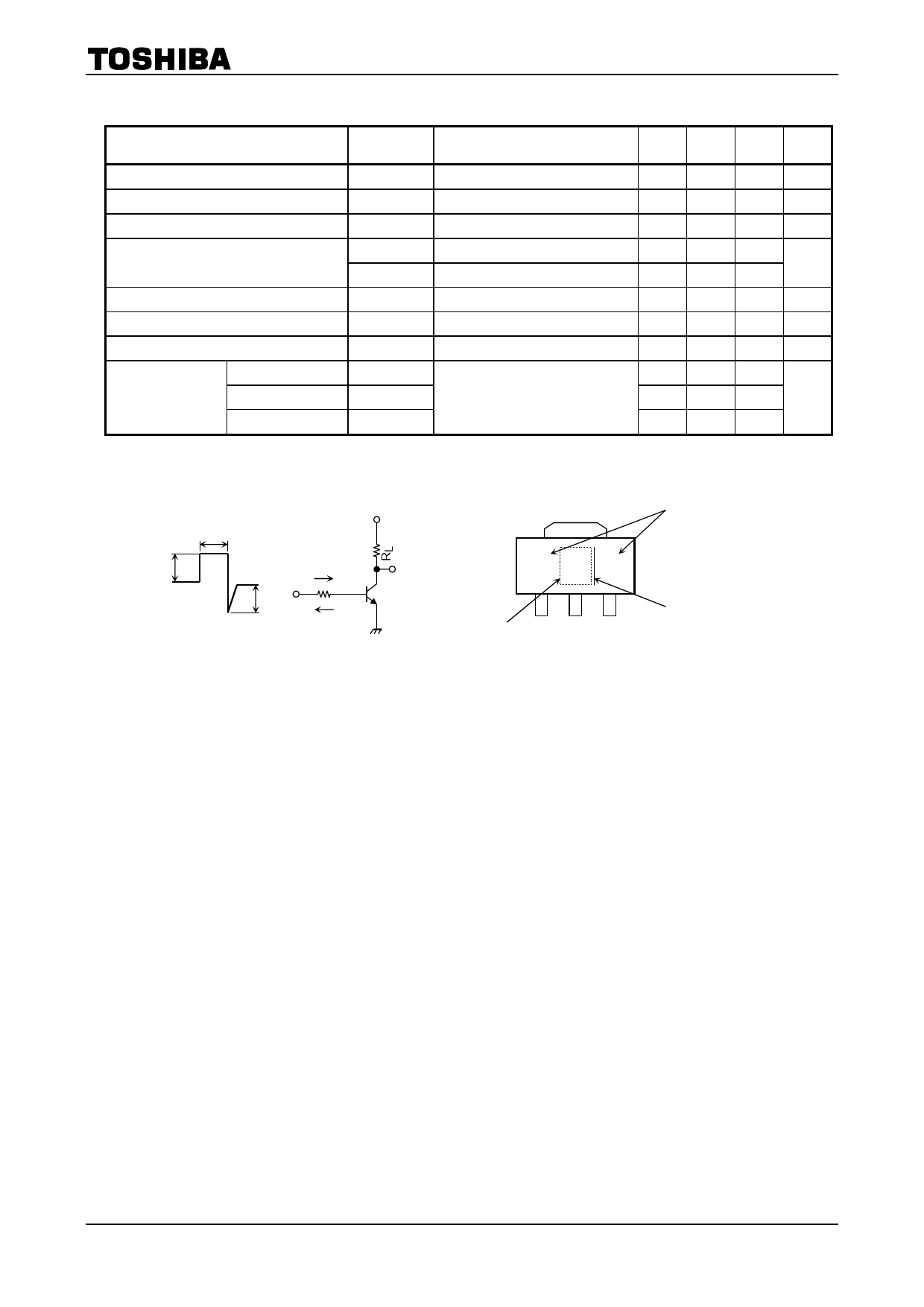
See Figure 1 circuit diagram.
VCC ∼− 12 V, RL = 7.5 Ω
IB1 = −IB2 = 53.3 mA
2SC5714
Min Typ. Max Unit
⎯
⎯
100
nA
⎯
⎯
100
nA
20
⎯
⎯
V
400 ⎯ 1000
200 ⎯
⎯
⎯
⎯
0.15
V
⎯
⎯
1.10
V
⎯
18
⎯
pF
⎯
100
⎯
⎯
350
⎯
ns
⎯
90
⎯
20 μs
IB1
IB1
Input
IB2
IB2
Duty cycle < 1%
VCC
Output
Marking
2E
Lot No.
Part No. (or abbreviation code)
A line indicates
lead (Pb)-free package or
lead (Pb)-free finish.
Figure 1 Switching Time Test Circuit &
Timing Chart
2
2006-11-10
Share Link: 