2SD1254(2003) データシートの表示(PDF) - Panasonic Corporation
部品番号
コンポーネント説明
メーカー
2SD1254 Datasheet PDF : 4 Pages
| |||
Power Transistors
2SD1254
Silicon NPN epitaxial planar type
For power switching
Complementary to 2SB0931
8.5±0.2
6.0±0.2
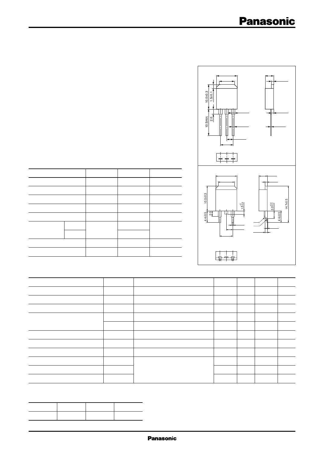
Unit: mm
3.4±0.3
1.0±0.1
■ Features
0 to 0.4
• Low collector-emitter saturation voltage VCE(sat)
0.8±0.1 R = 0.5
• Satisfactory linearity of forward current transfer ratio hFE
• Large collector current IC
• N type package enabling direct soldering of the radiating fin to the
printed circuit board, etc. of small electronic equipment.
2.54±0.3
1.4±0.1
5.08±0.5
R = 0.5
1.0±0.1
0.4±0.1
123
(8.5)
(6.0) 1.3
/ ■ Absolute Maximum Ratings TC = 25°C
e e) Parameter
Symbol Rating
Unit
c e. d typ Collector-base voltage (Emitter open) VCBO
130
V
n d stag tinue Collector-emitter voltage (Base open) VCEO
80
V
a e cle con Emitter-base voltage (Collector open) VEBO
7
V
lifecy , dis Collector current
IC
3
A
n u ct ped Peak collector current
ICP
6
A
te tin Produ ed ty Collectorpowerdissipation
PC
30
W
ur tinu Ta = 25°C
1.3
ing fo iscon Junction temperature
Tj
150
°C
in n llow d d Storage temperature
Tstg −55 to +150 °C
(6.5)
1 : Base
2 : Collector
3 : Emitter
N-G1 Package
Note) Self-supported type package is also prepared.
a o includestyfpoe, plane ■ Electrical Characteristics TC = 25°C ± 3°C
c ued nce Parameter
Symbol
Conditions
M is ntin tena Collector-emitter voltage (Base open)
/Disco main Collector-base cutoff current(Emitter open)
VCEO
ICBO
IC = 10 mA, IB = 0
VCB = 100 V,IE = 0
ce pe, Emitter-base cutoff current (Collector open)
D nan e ty Forward current transfer ratio
Maintientenanc Collector-emitter saturation voltage
d ma Base-emitter saturation voltage
(plane Transition frequency
IEBO
hFE1
hFE2 *
VCE(sat)
VBE(sat)
fT
VEB = 5 V,IC = 0
VCE = 2 V, IC = 0.1 A
VCE = 2 V, IC = 0.5 A
IC = 2 A, IB = 0.1 A
IC = 2 A, IB = 0.1 A
VCE = 10 V, IC = 0.5 A, f = 10 MHz
Min Typ Max Unit
80
V
10
µA
50
µA
45
60
260
0.5
V
1.5
V
30
MHz
Turn-on time
ton
IC = 0.5 A
0.5
µs
Storage time
tstg
IB1 = 50 mA, IB2 = − 50 mA
2.5
µs
Fall time
tf
VCC = 50 V
0.15
µs
Note) 1. Measuring methods are based on JAPANESE INDUSTRIAL STANDARD JIS C 7030 measuring methods for transistors.
2. *: Rank classification
Rank
R
Q
P
hFE2
60 to 120
90 to 180 130 to 260
Publication date: September 2003
SJD00171BED
1
Share Link: 