74AC174B データシートの表示(PDF) - STMicroelectronics
部品番号
コンポーネント説明
メーカー
74AC174B Datasheet PDF : 11 Pages
| |||
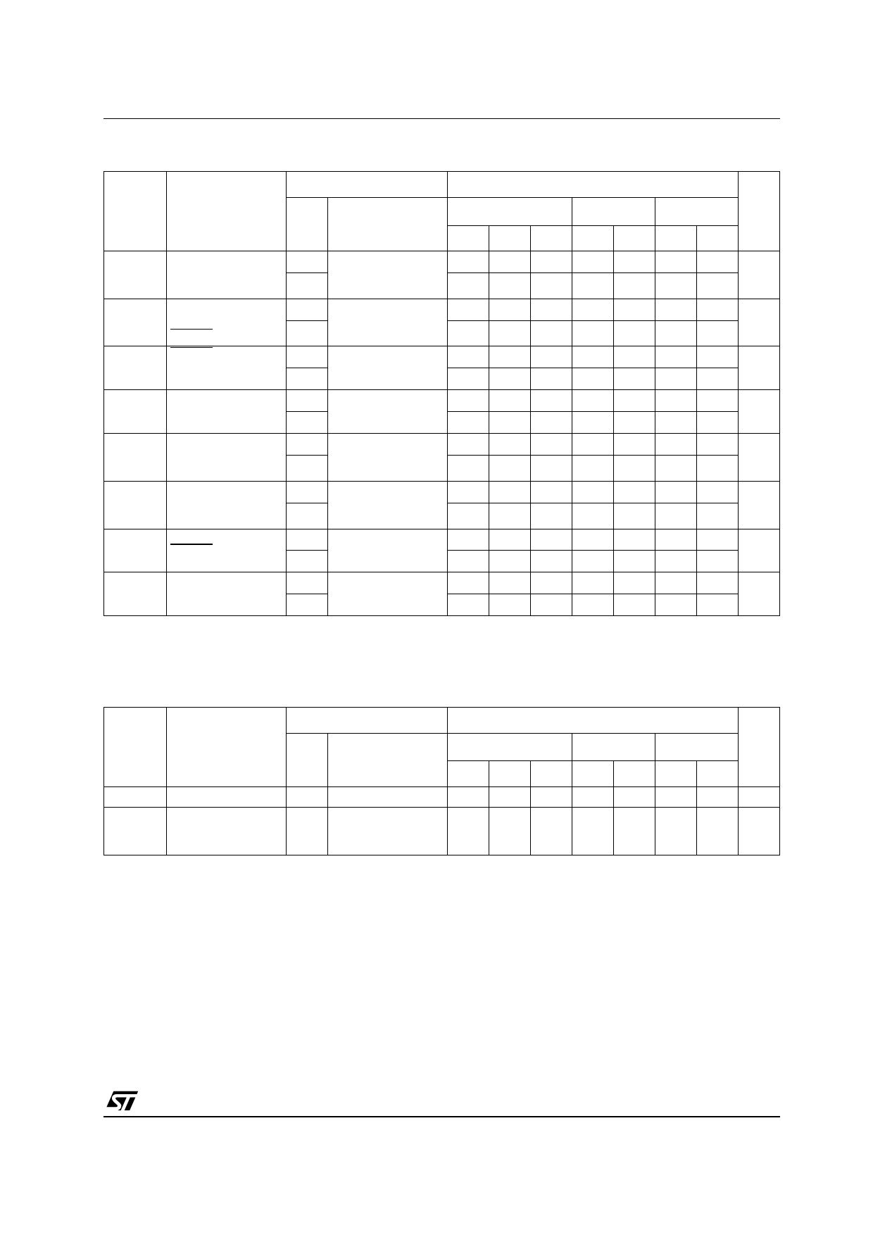
74AC174
AC ELECTRICAL CHARACTERISTICS (CL = 50 pF, RL = 500 Ω, Input tr = tf = 3ns)
Test Condition
Value
Symbol
Parameter
VCC
(V)
tPLH tPHL Propagation Delay
Time
CLOCK to Y
tPHL Propagation Delay
Time
CLEAR to Y
tWL CLEAR Pulse
Width, LOW
tW CLOCK Pulse
Width
ts
th
tREM
Setup Time D to
CLOCK, HIGH or
LOW
Hold Time D to
CLOCK, HIGH or
LOW
Recovery Time
CLEAR to CK
fMAX Maximum Clock
Frequency
3.3(*)
5.0(**)
3.3(*)
5.0(**)
3.3(*)
5.0(**)
3.3(*)
5.0(**)
3.3(*)
5.0(**)
3.3(*)
5.0(**)
3.3(*)
5.0(**)
3.3(*)
5.0(**)
TA = 25°C
-40 to 85°C -55 to 125°C Unit
Min. Typ. Max. Min. Max. Min. Max.
1.5 8.5 11.0
1.5 6.0 8.0
12.5
9.5
14.0
ns
10.5
1.5 9.0 11.5
1.5 7.0 9.0
12.5
10.5
13.5
ns
11.0
1.0 5.5
7.0
7.0
ns
1.0 5.0
5.0
5.0
1.0 5.5
7.0
7.0
ns
1.0 5.0
5.0
5.0
2.5 6.5
7.0
7.0
ns
2.0 5.0
5.5
5.5
1.0 3.0
3.0
3.0
ns
0.5 3.0
3.0
3.0
0 2.5
2.5
2.5
ns
0 2.0
2.0
2.0
90 200
70
70
MHz
100 250
100
100
(*) Voltage range is 3.3V ± 0.3V
(**) Voltage range is 5.0V ± 0.5V
CAPACITIVE CHARACTERISTICS
Test Condition
Value
Symbol
Parameter
VCC
(V)
TA = 25°C
-40 to 85°C -55 to 125°C Unit
Min. Typ. Max. Min. Max. Min. Max.
CIN Input Capacitance 5.0
4.5
pF
CPD Power Dissipation 5.0
Capacitance
fIN = 10MHz
33
pF
(note1)
1) CPD is defined as the value of the IC’s internal equivalent capacitance which is calculated from the operating current consumption without
load. (Refer to Test Circuit). Average operating current can be obtained by the following equation. ICC(opr) = CPD x VCC x fIN + ICC/6 (per circuit)
5/11
Share Link: 