KBPC3510G/W データシートの表示(PDF) - LiteOn Technology
部品番号
コンポーネント説明
メーカー
KBPC3510G/W Datasheet PDF : 2 Pages
| |||
LITE-ON
SEMICONDUCTOR
KBPC35005G(W) thru 3510G(W)
GLASS PASSIVATED BRIDGE RECTIFIERS
REVERSE VOLTAGE - 50 to 1000 Volts
FORWARD CURRENT - 35 Amperes
FEATURES
Rating to 1000V PRV
High efficiency
Glass passivated chip junction
Electrically isolated metal case for maximum heat
dissipation
UL recognized file # E95060
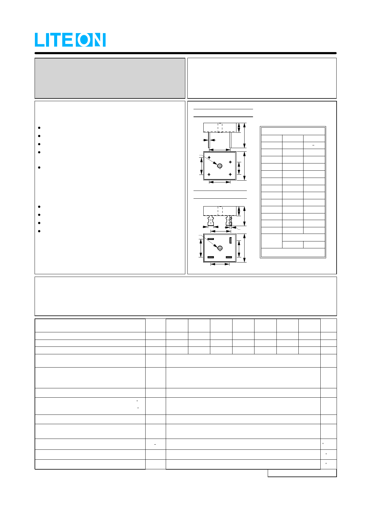
MECHANICAL DATA
Case : Mounted in the bridge encapsulation
Poarity : As marked on case
Mounting : Hole for # 10 screw
Weight : 0.85 ounces , 24.0 grams (terminal)
: 0.74 ounces , 21.0 grams (wire)
KBPC-GW (Wire)
E
N~
D
_
BA
D
+F
C
~
D
KBPC-G (Terminal)
BK
M
I
L
N
G~
_
J
+
C
~
KBPC-G/KBPC-GW
DIM. MIN. MAX.
A
31.80
B
7.90 8.40
C
28.30 28.80
D
17.60 18.60
E
0.97 1.07
F
10.90 11.90
G
17.60 18.60
H
13.80 14.80
I
16.10 17.10
J
16.10 17.10
K
18.80 21.30
L
0.76 0.86
M
6.30 6.50
HOLE FOR NO. 10 SCREW
N
5.08 5.59
All Dimensions in millimeter
MAXIMUM RATINGS AND ELECTRICAL CHARACTERISTICS
Ratings at 25℃ ambient temperature unless otherwise specified.
Single phase, half wave, 60Hz, resistive or inductive load.
For capacitive load, derate current by 20%
CHARACTERISTICS
Maximum Recurrent Peak Reverse Voltage
Maximum RMS Voltage
Maximum DC Blocking Voltage
Maximum Average Forward
Rectified Current
@TC =Ta
Peak Forward Surge Current
8.3ms single half sine-wave
super imposed on rated load
SYMBOL
KBPC35
005G/W
KBPC35
01G/W
KBPC35
02G/W
KBPC35
04G/W
KBPC35 KBPC35 KBPC35
06G/W 08G/W 10G/W
UNIT
VRRM
50
100
200
400
600
800 1000 V
VRMS
35
70
140
280
420
560
700
V
VDC
50
100
200
400
600
800 1000 V
I(AV)
35.0
A
IFSM
400
A
Maximum forward Voltage at 17.5A DC
VF
1.1
V
Maximum DC Reverse Current
at Rated DC Blocking Voltage
@TJ =25 C
@TJ =125 C
IR
5.0
500
uA
I 2 t Rating for fusing (t < 8.3ms), (Note 1)
I 2t
Typical Junction
Capacitance per element (Note 2)
CJ
660
A 2S
300
pF
Typical Thermal Resistance (Note 3, see Fig.1)
R0JC
Operating Temperature Range
TJ
Storage Temperature Range
TSTG
NOTES : 1.Measured at non-repetitive, for greater than 1ms and less than 8.3ms
2.Measured at 1.0MHz and applied reverse voltage of 4.0V DC.
3.Device mounted on 300mm x 300mm x 1.6mm Cu Plate Heatsink.
3.0
-55 to +150
-55 to +150
C/W
C
C
REV. 3, Apr-2007, KBDI03
Share Link: 