83C198 データシートの表示(PDF) - Intel
部品番号
コンポーネント説明
メーカー
83C198 Datasheet PDF : 19 Pages
| |||
8XC198
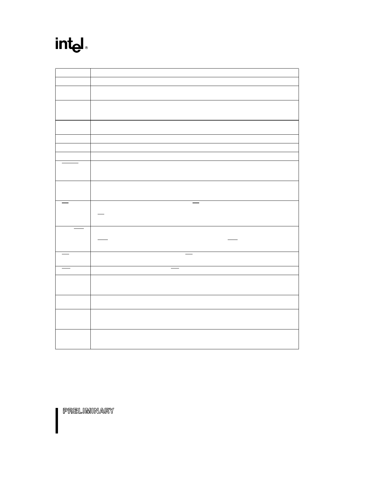
PIN DESCRIPTIONS
Symbol
Name and Function
VCC
Main supply voltage (5V)
VSS
The PLCC package has 5 VSS pins and the QFP package has 12 VSS pins All must be
connected to digital ground
VREF
Reference voltage for the A D converter (5V) VREF is also the supply voltage to the
analog portion of the A D converter and the logic used to read Port 0 Must be
connected for A D and Port 0 to function
ANGND
VPP
XTAL1
Reference ground for the A D converter Must be held at nominally the same potential
as VSS
Programming Voltage Also timing pin for the return from powerdown circuit
Input of the oscillator inverter and of the internal clock generator
XTAL2
Output of the oscillator inverter
RESET
Reset input to and open-drain output from the chip Input low for at least 4 state times to
reset the chip The subsequent low-to-high transition commences the 10-state Reset
Sequence
INST
Output high during an external memory read indicates the read is an instruction fetch
INST is valid throughout the bus cycle INST is activated only during external memory
accesses and output low for a data fetch
EA
Input for memory select (External Access) EA equal to a TTL-high causes memory
accesses to locations 2000H through 3FFFH to be directed to on-chip ROM EPROM
EA equal to a TTL-low causes accesses to these locations to be directed to off-chip
memory
ALE ADV
Address Latch Enable or Address Valid output as selected by CCR Both pin options
provide a latch to demultiplex the address from the address data bus When the pin is
ADV it goes inactive high at the end of the bus cycle ALE ADV is activated only during
external memory accesses
RD
Read signal output to external memory RD is activated only during external memory
reads
WR
Write output to external memory WR will go low for every external write
READY
Ready input to lengthen external memory cycles When the external memory is not
being used READY has no effect Internal control of the number of wait states inserted
into a bus cycle held not ready is available through configuration of CCR
HSI
Inputs to High Speed Input Unit Four HSI pins are available HSI 0 HSI 1 HSI 2 and
HSI 3 Two of them (HSI 2 and HSI 3) are shared with the HSO Unit
HSO
Outputs from High Speed Output Unit Six HSO pins are available HSO 0 HSO 1
HSO 2 HSO 3 HSO 4 and HSO 5 Two of them (HSO 4 and HSO 5) are shared with the
HSI Unit
Port 0
4-bit high impedance input-only port These pins can be used as digital inputs and or as
analog inputs to the on-chip A D converter These pins set the Programming Mode on
the EPROM device
5
Share Link: 