85HFR20 データシートの表示(PDF) - International Rectifier
部品番号
コンポーネント説明
メーカー
85HFR20 Datasheet PDF : 8 Pages
| |||
85HF(R) Series
Bulletin I20203 rev. A 09/98
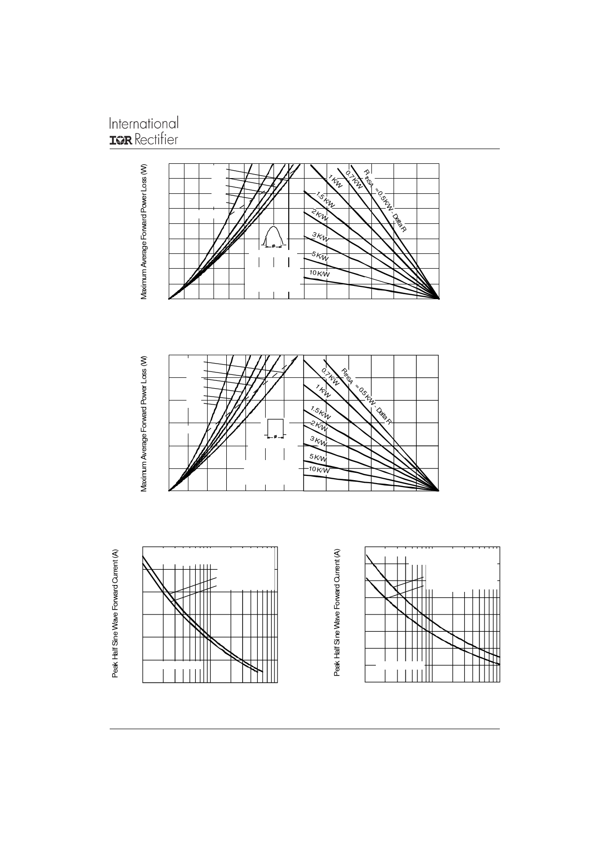
90
180°
80
120°
90°
70
60°
30°
60
RMS Limit
50
40
1.5 K/W
2 K/W
3 K/W
30
Conduction Angle
5 K/W
20
85HF(R) Series 10 K/W
(1400V to 1600V)
10
TJ = 150°C
0
0 10 20 30 40 50 60 70 80 900 25 50 75 100 125 150
Average Forward Current (A)
Maximum Allowable Ambient Temperature (°C)
Fig. 7 - Forward Power Loss Characteristics
120
DC
180°
100
120°
90°
60°
80
30°
60
RMS Limit
40
Conduction Period
0.7 K/W
1 K/W
1.5 K/W
2 K/W
3 K/W
5 K/W
20
85HF(R) Series
(1400V to 1600V)
10 K/W
TJ = 150°C
0
0 20 40 60 80 100 120 1040 25 50
75 100 125 150
Average Forward Current (A)
Maximum Allowable Ambient Temperature (°C)
Fig. 8 - Forward Power Loss Characteristics
1600
1400
1200
At Any Rated Load Condition And With
Rated VRRM Applied Following Surge.
Initial TJ= TJ Max.
@ 60 Hz 0.0083 s
@ 50 Hz 0.0100 s
1000
800
600
85HF(R) Series
400
1
10
100
Number Of Equal Amplitude Half Cycle Current Pulses (N)
Fig. 9 - Maximum Non-Repetitive Surge Current
www.irf.com
1800
1600
1400
1200
Maximum Non Repetitive Surge Current
Versus Pulse Train Duration.
Initial TJ = TJ Max.
No Voltage Reapplied
Rated VRRM Reapplied
1000
800
600
400 85HF(R) Series
200
0.01
0.1
1
Pulse Train Duration (s)
Fig. 10 - Maximum Non-Repetitive Surge Current
7
Share Link: 