RMWP23001 データシートの表示(PDF) - Raytheon Company
部品番号
コンポーネント説明
メーカー
RMWP23001 Datasheet PDF : 7 Pages
| |||
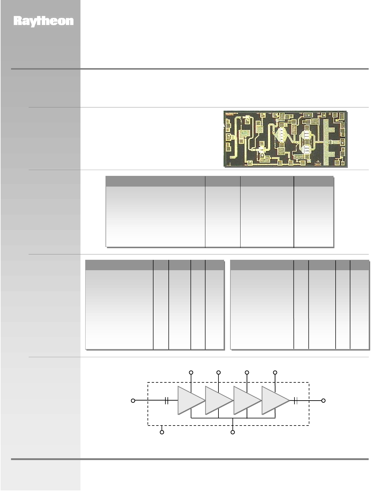
RMWP23001
21-24 GHz Power Amplifier MMIC
Description
Features
PRODUCT INFORMATION
The RMWP23001 is a 4-stage GaAs MMIC amplifier designed as a 21 to 24 GHz Power Amplifier for use in point to
point radios, point to multi-point communications, LMDS, and other millimeter wave applications. In conjunction
with other Raytheon amplifiers, multipliers and mixers it forms part of a complete 23 GHz transmit/receive chipset.
The RMWP23001 utilizes Raytheon’s 0.25µm power PHEMT process and is sufficiently versatile to serve in a
variety of power amplifier applications.
4 mil substrate
Small-signal gain 22.5 dB (typ.)
1dB compressed Pout 23.5 dBm (typ.)
Chip size 2.6 mm x 1.2 mm
Absolute
Maximum
Ratings
Parameter
Positive DC voltage (+4 V Typical)
Negative DC voltage
Simultaneous (Vd - Vg)
Positive DC Current
RF Input Power (from 50 Ω source)
Operating Baseplate Temperature
Storage Temperature Range
Thermal Resistance (Channel to Backside)
Symbol
Vd
Vg
Vdg
ID
PIN
TC
Tstg
Rjc
Value
+6
-2
8
607
+8
-30 to +85
-55 to +125
36.5
Units
Volts
Volts
Volts
mA
dBm
°C
°C
°C/W
Electrical
Characteristics
(At 25°C),
50 Ω system,
Vd = +4 V,
Quiescent Current
Idq = 400 mA
Parameter
Min Typ Max Unit
Frequency Range
21
24 GHz
Gate Supply Voltage (Vg)1
-0.3
V
Gain Small Signal at
Pi n= -8 dBm
20 22.5
dB
Gain Variation vs. Frequency
1.0
dB
Gain at 1dB Compression
21.5
dB
Power Output at 1dB
Compression
24
dBm
Power Output Saturated:
Pin = +3 dBm
22 25
dBm
Drain Current at Pin = -8 dBm
400
mA
Parameter
Min Typ Max Unit
Drain Current at 1 dB
Compression
430
mA
Drain Current at Saturated:
Pin = +3 dBm
410
mA
Power Added Efficiency
(PAE): at P1 dB
15
%
Input Return Loss
(Pin = -8 dBm)
14
dB
Output Return Loss
(Pin = -8 dBm)
12
dB
OIP3
33
dBm
Noise Figure
8
dB
Functional
Block Diagram
RF IN
MMIC Chip
Drain
Supply
Vd1
Drain
Supply
Vd2
Drain
Supply
Vd3
Drain
Supply
Vd4
RF OUT
www.raytheon.com/micro
Ground
Note:
(Back of Chip)
1. Typical range of gate voltage is -0.7 to -0.05 V to set Idq of 400 mA.
Gate Supply
Vg
Characteristic performance data and specifications are subject to change without notice.
Revised March 14, 2001
Page 1
Raytheon RF Components
362 Lowell Street
Andover, MA 01810
Share Link: 