A1359 データシートの表示(PDF) - Allegro MicroSystems
部品番号
コンポーネント説明
メーカー
A1359 Datasheet PDF : 12 Pages
| |||
A1359
Factory-Programmed Dual Output Linear Hall Effect Sensor IC
With Analog and Pulse Width Modulated Outputs
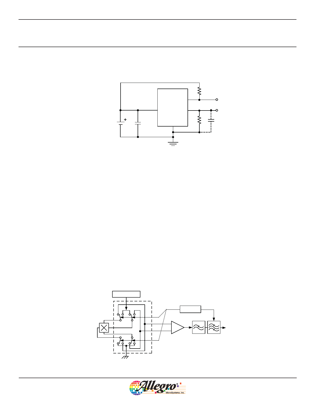
Typical Application Circuit
A1359
PWMOUT
RPULLUP
VCC
VOUT
5V
0.1 μF
GND
RL
CL
4.7 nF
Optional: Recommended
for EMC robustness
Figure 7. Typical application circuit
Chopper Stabilization Technique
When using Hall-effect technology, a limiting factor for
switchpoint accuracy is the small signal voltage developed across
the Hall element. This voltage is disproportionally small relative
to the offset that can be produced at the output of the Hall sensor
IC. This makes it difficult to process the signal while maintain-
ing an accurate, reliable output over the specified operating
temperature and voltage ranges. Chopper stabilization is a unique
approach used to minimize Hall offset on the chip. Allegro
employs a patented technique to remove key sources of the out-
put drift induced by thermal and mechanical stresses. This offset
reduction technique is based on a signal modulation-demodula-
tion process. The undesired offset signal is separated from the
magnetic field-induced signal in the frequency domain, through
modulation. The subsequent demodulation acts as a modulation
process for the offset, causing the magnetic field-induced signal
to recover its original spectrum at base band, while the DC offset
becomes a high-frequency signal. The magnetic-sourced signal
then can pass through a low-pass filter, while the modulated DC
offset is suppressed. In addition to the removal of the thermal and
stress related offset, this novel technique also reduces the amount
of thermal noise in the Hall sensor while completely removing
the modulated residue resulting from the chopper operation. The
chopper stabilization technique uses a high frequency sampling
clock. For demodulation process, a sample-and-hold technique
is used. This high-frequency operation allows a greater sampling
rate, which results in higher accuracy and faster signal-processing
capability. This approach desensitizes the chip to the effects
of thermal and mechanical stresses, and produces devices that
have extremely stable quiescent Hall output voltages and precise
recoverability after temperature cycling. This technique is made
possible through the use of a BiCMOS process, which allows the
use of low-offset, low-noise amplifiers in combination with high-
density logic integration and sample-and-hold circuits.
Regulator
Hall Element
Clock/Logic
Amp
Anti-aliasing Tuned
LP Filter Filter
Figure 8. Concept of chopper stabilization technique
Allegro MicroSystems, Inc.
10
115 Northeast Cutoff
Worcester, Massachusetts 01615-0036 U.S.A.
1.508.853.5000; www.allegromicro.com
Share Link: 