A1359 データシートの表示(PDF) - Allegro MicroSystems
部品番号
コンポーネント説明
メーカー
A1359 Datasheet PDF : 12 Pages
| |||
A1359
Factory-Programmed Dual Output Linear Hall Effect Sensor IC
With Analog and Pulse Width Modulated Outputs
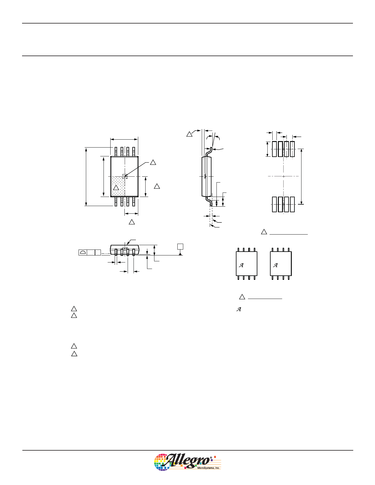
Package LE, 8-Pin TSSOP
3.00±0.10
E
8
6.40 BSC 4.40±0.10
A
D
2.20 D
12
1.50
D
8X
0.10 C
0.30
0.19
0.65 BSC
Branded Face
C
SEATING
PLANE
1.10 MAX
0.15
0.05
For Reference Only; not for tooling use (reference MO-153 AA)
Dimensions in millimeters
Dimensions exclusive of mold flash, gate burrs, and dambar protrusions
Exact case and lead configuration at supplier discretion within limits shown
A Terminal #1 mark area
B Reference land pattern layout (reference IPC7351 SOP65P640X110-8M);
All pads a minimum of 0.20 mm from all adjacent pads; adjust as
necessary to meet application process requirements and PCB layout
tolerances; when mounting on a multilayer PCB, thermal vias can improve
thermal dissipation (reference EIA/JEDEC Standard JESD51-5)
Branding scale and appearance at supplier discretion
D Hall element, not to scale
E Active Area Depth 0.36 mm REF
0.45
8º
0.65
0º
8
0.20
0.09
1.70
6.10
0.60
+0.15
–0.10
1.00 REF
0.25 BSC
SEATING PLANE
GAUGE PLANE
12
B PCB Layout Reference View
359
YYWW
59R
YYWW
1
A1359LLETR-T
1
A1359LLETR-RP-T
C Branding Reference View
Top line is device designator
= Supplier emblem
Y = Last two digits of year of manufacture
W = Week of manufacture
Allegro MicroSystems, Inc.
11
115 Northeast Cutoff
Worcester, Massachusetts 01615-0036 U.S.A.
1.508.853.5000; www.allegromicro.com
Share Link: 