A3950 データシートの表示(PDF) - Allegro MicroSystems
部品番号
コンポーネント説明
メーカー
A3950 Datasheet PDF : 9 Pages
| |||
Preliminary Data Sheet
Subject to Change without Notice
November 4, 2005
A3950
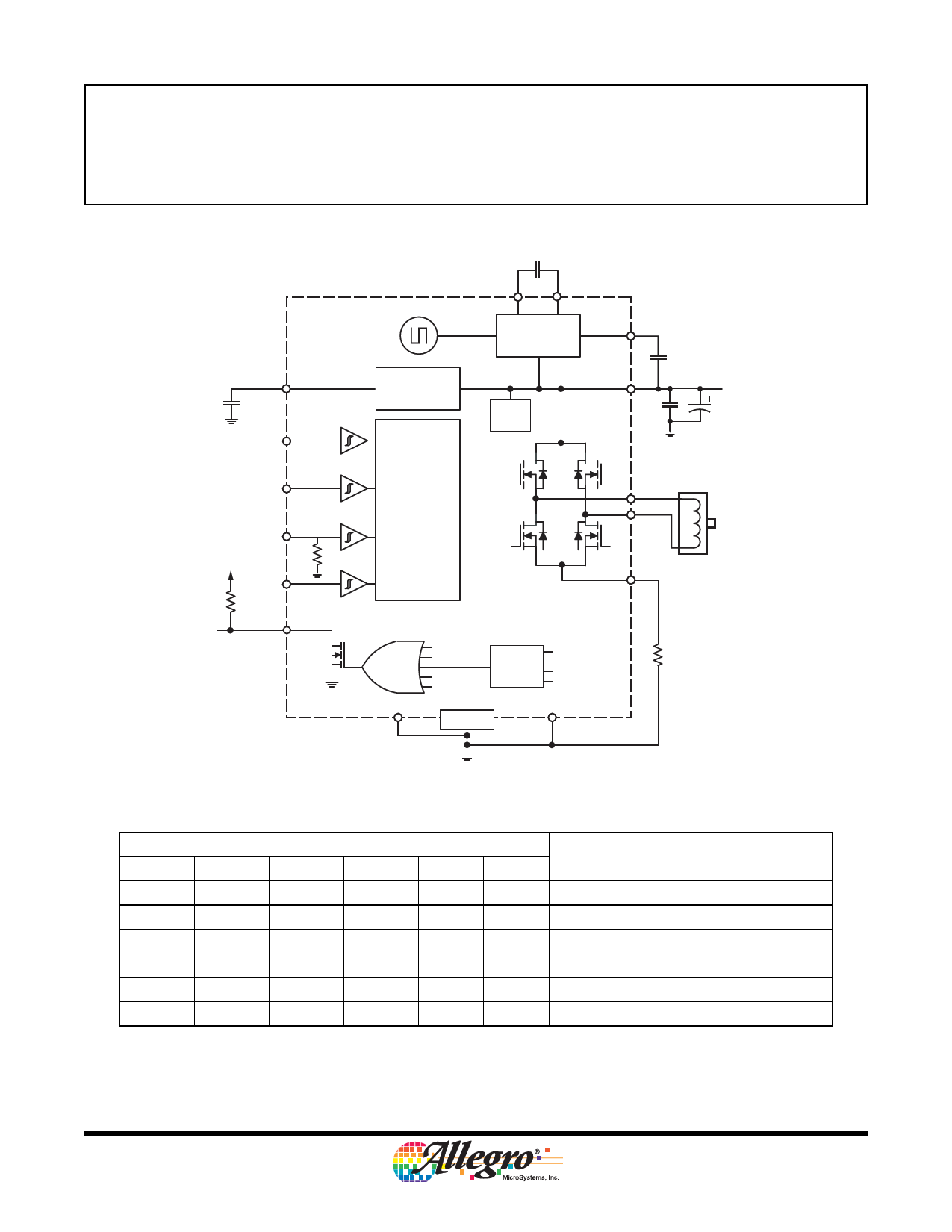
DMOS Full-Bridge Motor Driver
Functional Block Diagram
CP1
0.1 µF
CP2
VREG
22 µF
25 V
MODE
Low-Side
Gate Supply
Charge
Pump
Bias
Supply
VCP
VBB
0.1 µF
Load Supply
0.1 µF
100 µF
PHASE
ENABLE
SLEEP
Control Logic
OUTA
OUTB
SENSE
NFAULT
GND
UVLO
STB
STG
TSD Warning
Motor Lead
Protection
VBB
OUTA
OUTB
SENSE
Pad
GND
RSENSE
Control Logic Table1
PHASE ENABLE
Pin
MODE SLEEP
OUTA
OUTB
Function
1
1
X
1
H
L Forward
0
1
X
1
L
H Reverse
X
0
1
1
L
L Brake (slow decay)
1
0
0
1
L
H Fast Decay Synchronous Rectification2
0
0
0
1
H
L
Fast Decay Synchronous Rectification2
X
X
X
0
Z
Z
Sleep Mode
1X iindicates “don’t care,” Z indicates high impedence.
2To prevent reversal of current during fast decay synchronous rectification, outputs go to the high impedance state as the current approaches 0 A.
A3950DS
Allegro MicroSystems, Inc.
2
115 Northeast Cutoff, Box 15036
Worcester, Massachusetts 01615-0036 (508) 853-5000
www.allegromicro.com
Share Link: 