A3903 データシートの表示(PDF) - Allegro MicroSystems
部品番号
コンポーネント説明
メーカー
A3903 Datasheet PDF : 8 Pages
| |||
A3903
Low Voltage DC Motor Driver
during PWM operation and ensure that the supply
voltage remains stable at the input terminal. Bulk
capacitance is often located at a non-ideal distance
from the device. If the recommended capacitance of
10 μF cannot be located very close to the supply ter-
minal on the A3903, it is recommended that a 0.1 μF
capacitor be placed as close to the VDD terminal as
possible to provide a path for transient currents.
PWM Operation
In some applications current control may be desired.
Pulse width modulating the inputs will allow the
output current to be regulated. When external PWM
control is used, the VREF pin should be connected
directly to the VSET pin. This effectively disables
voltage control on the source driver, and allows
maximum current to flow through the driver. Current
is then controlled using enable chopping, described
below.
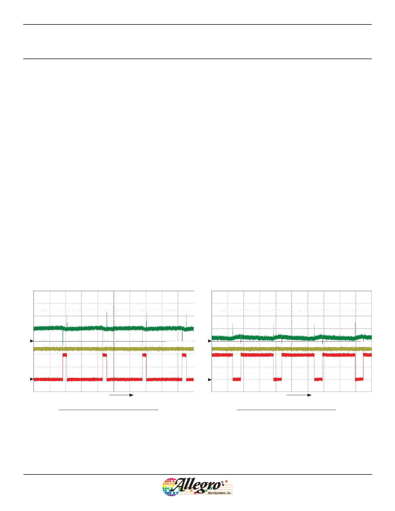
Enable Chopping By PWMing the logic inputs
between enable and brake modes, the current in the
motor winding can be controlled. It is accomplished
by holding one input high while PWMing the other
input. During the on-cycle, current flows in the bridge
consistent with the direction programmed on the input
pins. During the off-cycle, the A3903 enters brake
mode. Enable chopping is illustrated in figure 1.
Current in the motor winding is controlled by chang-
ing the duty cycle on the PWM input. As shown
in figure 2, the average current is still positive but,
because the duty cycle is less, the average current is
much lower.
IOUT
IOUT
C3
VIN1
C3
VIN1
VIN2
C1
C1
C2
VIN2
C2
t
t
Symbol
C1
C2
C3
t
Parameter
VIN1
VIN2
IOUT
time
Units/Division
2V
2V
100 mA
20 μs
Symbol
C1
C2
C3
t
Parameter
VIN1
VIN2
IOUT
time
Units/Division
2V
2V
100 mA
20 μs
Figure 1. Enable chopping. Forward direction, output duty cycle 90%.
Figure 2. Enable chopping. Forward direction, output duty cycle 20%.
Allegro MicroSystems, Inc.
7
115 Northeast Cutoff
Worcester, Massachusetts 01615-0036 U.S.A.
1.508.853.5000; www.allegromicro.com
Share Link: 