ACS1/085S データシートの表示(PDF) - STMicroelectronics
部品番号
コンポーネント説明
メーカー
ACS1/085S Datasheet PDF : 8 Pages
| |||
ACS108-5Sx
HIGH INDUCTIVE SWITCH-OFF OPERATION
At the end of the last conduction half-cycle, the load current reaches the holding current level IH, and the
ACS™ switch turns off. Because of the inductance L of the load, the current flows through the avalanche
diode D and decreases linearly to zero. During this time, the voltage across the switch is limited to the
clamping voltage VCL.
The energy stored in the inductance of the load depends on the holding current IH and the inductance (up
to 10 H); it can reach about 20 mJ and is dissipated in the clamping section that is especially designed for
that purpose.
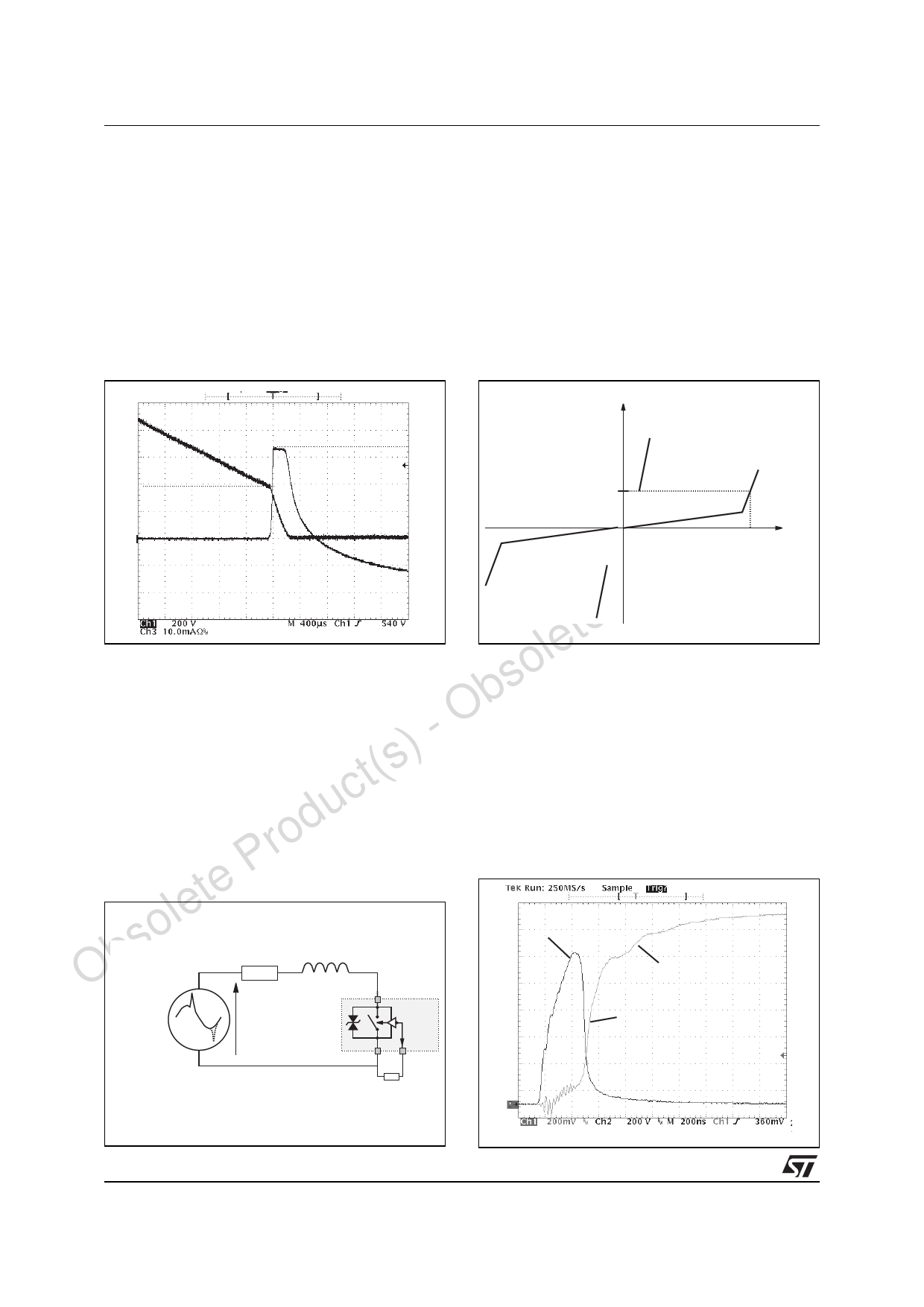
Fig. 1: Turn-off operation of the ACS108 switch
with an electro valve: waveform of the gate current
IG, pin OUT current IOUT & voltage VOUT.
Fig. 2: ACS108 switch static characteristic.
IOUT
(10 mA/div)
VCL = 650V
IOUT
IH
ct(s) VOUT
Produ (200V/div)
Time (400µs/div)
IH
VCL
VOUT
lete AC LINE TRANSIENT VOLTAGE RUGGEDNESS
so The ACS108 switch is able to safely withstand the AC line transient voltages either by clamping the low
b energy spikes or by breaking over under high energy shocks.
O The test circuit in Figure 4 is representative of the final ACS™ application and is also used to stress the
- ACS™ switch according to the IEC61000-4-5 standard conditions. Thanks to the load, the ACS™ switch
t(s) withstands the voltage spikes up to 2 kV above the peak line voltage. It will break over safely even on resis-
tive load where the turn-on current rise is high as shown in Figure 4. Such non-repetitive testing can be
c done 10 times on each AC line voltage polarity.
du Fig. 3: Overvoltage ruggedness test circuit for resis-
ro tive and inductive loads according to IEC61000-4-5
P standard.
te R = 150Ω, L = 5µH, VPP = 2kV.
Fig. 4: Current and voltage of the ACS™ during
IEC61000-4-5 standard test with a 150Ω - 10µH
load & VPP = 2kV.
Obsole R
L
Vout (200 V/div)
Iout (2 A/div)
OUT
AC LINE &
SURGE VOLTAGE
GENERATOR
VAC + VPP
S
ON
D
ACSxx
dI/dt = 100 A/µs
COM
G
RG= 220Ω
4/8
®
Share Link: 