ACS1/085S データシートの表示(PDF) - STMicroelectronics
部品番号
コンポーネント説明
メーカー
ACS1/085S Datasheet PDF : 8 Pages
| |||
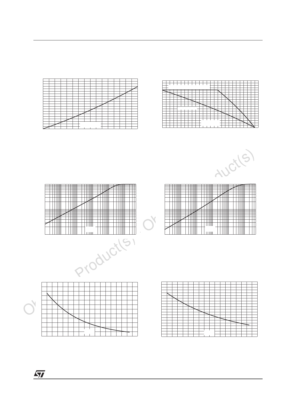
ACS108-5Sx
Fig. 5: Maximum power dissipation versus RMS
on-state current.
Fig. 6: RMS on-state current versus ambient
temperature.
P(W)
1.0
0.9
0.8
0.7
0.6
0.5
0.4
0.3
0.2
0.1
IT(RMS)(A)
0.0
0.0 0.1 0.2 0.3 0.4 0.5 0.6 0.7 0.8
IT(RMS)(A)
1.0
0.9
0.8
0.7
0.6
0.5
0.4
0.3
0.2
0.1
0.0
0
ACS108-5SA (TO92, Tamb=Tlead)
ACS108-5SN with 5cm² copper surface under tab
ACS108-5SA (TO92)
Tamb(°C)
10 20 30 40 50 60 70 80 90 100 110 120 130
Fig. 7-1: Relative variation of thermal impedance
) junction to ambient versus pulse duration
t(s (ACS108-5SA) (TO-92).
Fig. 7-2: Relative variation of thermal impedance
junction to ambient versus pulse duration
(ACS108-5SN) (SOT-223).
uc Zth(j-a) / Rth(j-a)
d 1.00
Zth(j-a) / Rth(j-a)
1.00
lete Pro 0.10
0.10
Obso 0.01
- 1E-3
1E-2
tp(s)
1E-1 1E+0
1E+1
1E+2 5E+2
0.01
1E-3
1E-2
tp(s)
1E-1 1E+0
1E+1
1E+2 5E+2
ct(s) Fig. 8: Relative variation of gate trigger current
u versus junction temperature.
Fig. 9: Relative variation of holding and latch-
ing current versus junction temperature.
Prod IGT [Tj] / IGT [Tj=25°C]
3.0
te 2.5
ole 2.0
Obs1.5
IH,IL [Tj] / IH,IL [Tj=25°C]
2.0
1.8
1.6
1.4
1.2
1.0
0.8
1.0
0.6
0.5
0.0
-40 -20 0
Tj(°C)
20 40 60 80 100 120 140
0.4
0.2
0.0
-40 -20 0
Tj(°C)
20 40 60 80 100 120 140
5/8
®
Share Link: 